mstechca
New Member
I have found the following:
**broken link removed**
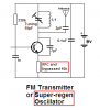
Talking electronics declares this a typical FM transmitter.
For my receiver, I made the oscillator circuit in such a way that the tank circuit is connected to ground instead of VCC. Why? because I wanted to achieve higher gain. and I'm sure a common emitter amplifier is better than a common collector one. and I can tell that it is a common base amplifier for AC.
But here is the question. If a receiver can almost be built the same way as a transmitter, and a receiver can cause interference (a.k.a. transmit signals), then why isn't there just an extremely simple method for me to take the transmitter above and convert it to a receiver without adding extra components (with the exception of the audio amplifier)?
and if there is, I would like to know, because my receiver partially uses this design.
**broken link removed**
Talking electronics declares this a typical FM transmitter.
For my receiver, I made the oscillator circuit in such a way that the tank circuit is connected to ground instead of VCC. Why? because I wanted to achieve higher gain. and I'm sure a common emitter amplifier is better than a common collector one. and I can tell that it is a common base amplifier for AC.
But here is the question. If a receiver can almost be built the same way as a transmitter, and a receiver can cause interference (a.k.a. transmit signals), then why isn't there just an extremely simple method for me to take the transmitter above and convert it to a receiver without adding extra components (with the exception of the audio amplifier)?
and if there is, I would like to know, because my receiver partially uses this design.