Continue to Site

Welcome to our site!

Electro Tech is an online community (with over 170,000 members) who enjoy talking about and building electronic circuits, projects and gadgets. To participate you need to register. Registration is free. Click here to register now.

  • Welcome to our site! Electro Tech is an online community (with over 170,000 members) who enjoy talking about and building electronic circuits, projects and gadgets. To participate you need to register. Registration is free. Click here to register now.

InfraredChannel

Status
Not open for further replies.
QuickStrike said:
Very concerned about this problem:

At Node A, I measure the amplitude of the square wave at 30-200 KHz and it is 5V, however when I pick up the frequency to 3MHz the amplitude goes down to 50mV and it looks like a triangle rather than a square wave.

Too high a frequency for the components you're using.

How can I keep the signal from loosing shape and amplitude at 3MHz or higher frequencies?

Use better components, it's hard to say if it's the IR LED or the photodiode, and it may well be both?.

I’m thinking maybe a transimpedance amplifier will probably work better since it will amplify the current to voltage rather than just using the voltage at A.

I don't see any relevence at all?.

Not too concerned about the following questions:

At C there is a DC offset and at D, the DC offset if even bigger, can this be solved?

Why should you want to?, it's a single ended driver, pulled up to 5V, it's supposed to be offset from zero - and what difference does it make?.

Also at C & D there is an overshoot when signal goes high and also when goes low, can this be solved?

I wouldn't have thought so, and again, what difference does it make?.

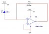
Note: I'm not using the same voltage comparator and mosfet shown below.
 
Shouldn't the photodiode's polarity be reversed? The way it is shown it is conducting all the time.
With it reversed, it would not conduct and node A would be low until IR radiation makes it leak current and node A would be high.
 
audioguru said:
Shouldn't the photodiode's polarity be reversed? The way it is shown it is conducting all the time.
With it reversed, it would not conduct and node A would be low until IR radiation makes it leak current and node A would be high.

Yes, he's got the photodiode the wrong way round, also he's not biased the input of the comparator as I suggested previously.
 
audioguru wrote:
"Shouldn't the photodiode's polarity be reversed? The way it is shown it is conducting all the time. With it reversed, it would not conduct and node A would be low until IR radiation makes it leak current and node A would be high."

Nigel Goodwin wrote:
"Yes, he's got the photodiode the wrong way round, also he's not biased the input of the comparator as I suggested previously."


U r both correct, I just drew the circuit wrong, but I have it in reverse bias on the breedboard.

Nigel Goodwin wrote:
"also he's not biased the input of the comparator as I suggested previously."


I don't understand when u say "bias the input of the comparator", u mean put a resistor after C1 going connected to ground?

How does biasing the input of the comparator help?

Nigel Goodwin wrote:
"Too high a frequency for the components you're using. "


Tr = Rise time
Tf = Fall Time

The led emitter (sfh4501) I'm using has a Tr and Tf of 10ns.
The led detector (sfh203) has a Tr and Tf of 5ns.
The voltage comparator (AD8564AN) has a tpd of 8ns.
 
QuickStrike said:
I don't understand when u say "bias the input of the comparator", u mean put a resistor after C1 going connected to ground?

Two resistors, one to ground, the other to positive. Use much higher resistors than you have on the other input.

How does biasing the input of the comparator help?

A comparator compares the two inputs, if they are already very close only a small signal will make it switch, you can make one of the four resistors a variable one to adjust the switching point.

Nigel Goodwin wrote:
"Too high a frequency for the components you're using. "


Tr = Rise time
Tf = Fall Time

The led emitter (sfh4501) I'm using has a Tr and Tf of 10ns.
The led detector (sfh203) has a Tr and Tf of 5ns.
The voltage comparator (AD8564AN) has a tpd of 8ns.

Each half cycle at 3MHz only last 167uS, you've then got all the limitations of those three components, plus the drive transistor, and plus the original drive waveform - the 3MHz squarewave won't be perfect.

I'd be inclined to study the photodiode datasheet, try and find under what conditions it works best?, do the same with the LED as well.
 
If I connect a transimpedance amplifier to the photodiode, this will convert current to voltage and amplify it, right?

Confused on this now!!

Do we want to convert the "leakage current = photocurrent" of the photodiode or the current being drawn from the power supply by Rf or both.

In other words, which current do we want to convert to voltage? the photocurrent or the current coming from the +5V power supply which is being drawn by Rf? or both?
 

Attachments

  • image2_141.jpg
    image2_141.jpg
    11 KB · Views: 642
Hi QuickStrike,

The following webpage tells about the limitation and pitfalls in working with photodiode and photoamplifiers. Worth a look at the presentation pdf.

**broken link removed**
 
In the figure "Infra1.jpg", how do u calculate the value of C1?

Do u use the equation: (f=1/2PiRC)?

I only need to pass frequencies in the range of 50Hz to 2 MHz, so what value do I choose for f and what does that value exactly mean?

Does it mean the Cut Off frequency and does that it will attenuate the frequency below or above that Cut Off Frequency?
 
Hi Quickstrike,
If you don't turn around the photodiode and add a voltage divider with two resistors at pin 4 like pin 5 has, then the circuit won't work.

Then C1 would make a highpass filter (passes high frequencies and attenuates low frequencies) with the series combination of the source resistance of the photodiode in parallel with R2, and the parallel resistance of the two new voltage divider resistors. Then the response would be down 3dB at the cutoff frequency using your correct formula.
 
Status
Not open for further replies.

Latest threads

New Articles From Microcontroller Tips

Back
Top