Continue to Site

Welcome to our site!

Electro Tech is an online community (with over 170,000 members) who enjoy talking about and building electronic circuits, projects and gadgets. To participate you need to register. Registration is free. Click here to register now.

  • Welcome to our site! Electro Tech is an online community (with over 170,000 members) who enjoy talking about and building electronic circuits, projects and gadgets. To participate you need to register. Registration is free. Click here to register now.

Drawing Schematic Diagram

Status
Not open for further replies.

beginner2

New Member
ermm...
maybe this is a bit off topic....
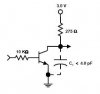
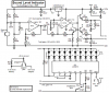
but i wanna ask what program can i use in order to draw a digram like below? or like those diagrams which we can find in any reference book?

I try to use MS Words and Pspice to draw but wasnt so satisfy with it.

Any suggestion?
 

Attachments

  • untitled_203.jpg
    untitled_203.jpg
    5 KB · Views: 850
I use Microsoft Paint to make schematics by copying and pasting parts from other schematics and holding down the SHIFT key to make straight lines like in this schematic:
 

Attachments

  • sound_level_indicator_schematic_rev1.png
    sound_level_indicator_schematic_rev1.png
    65.7 KB · Views: 2,801
i suggest Eagle. best one i know. and you can make PCB layouts with it also from the shematics you make there.
 
word-art :D
seriouly I do actually use wordart for schematics, its not to bad, group a few lines together for common cct (OPAMP, diff-amp)

I have actually started using Inkscape a bit more though for schematic drawing.

I have OrCAD at work and eqaually EAGLE at home, I just dont like the symbols for showing in a report or in a post, the lines are too thin
 
Eagle CAD and Circuit Maker are very simple for me.

I wrote a search program for Eagle CAD that I run and just type in the part I can't find and it tells me the Eagle library it is in, as their library arrangement (IMHO) is sometimes confusing. But for the price I can deal with it..
 
I use Ivex Winboard.

Everyone (except for Audioguru, since he is natural :lol: ) is trying to tell you that the best way to go to draw schematics is to use an Electronics CAD program. CAD = Computer Aided Design.

You know you got one when you have electronic components, and basically, you pick and place components and connect them with wires. It's just like drawing lines on a piece of paper, and gluing components on.

Well Audioguru, I shall congratulate you for being able to draw perfect schematics in paint, BUT there is a problem. If you do it in paint, how would you be able to make a PCB, and make a netlist? Manually? :shock:

if I were to take your path, I might as well use pencil and paper, and photocopy the most-often used components. Is there a reason why you can't use an electronics CAD program?

Styx, You are kind-of on the same route as Audioguru when you mention word-art, but at least you can add and remove components without manually erasing it.
 
Your best choice is a cad program like eagle because it's free,widely used by lot's of people and it has a huge library of part's and it is easy to learn.
And finally you can make your PCB from your schematic which is the reason for drawing the schematic in the first place right?
There's always more than one road to take so you might as well take the easy one and do everyting in one program.
 
mstechca said:
Well Audioguru, I shall congratulate you for being able to draw perfect schematics in paint, BUT there is a problem. If you do it in paint, how would you be able to make a PCB, and make a netlist? Manually?
Thanks, but I use graph-paper and an eraser to make a Veroboard or stripboard parts layout for my prototypes. When I needed many pcb's for a work project then I send my schematic and prototype to a local pcb design/make company for them to professionally make double-sided pcb's, usually using surface-mounted devices and they install the parts on the pcb's too.
Many very complex one-off projects for work have been made by me on Veroboard.
 
Like I said there's many roads leading to the same place,a finnished PCB.
In the end it all comes back to somebody using a CAD program,but everybody has to do it the way their most comfortable with.

Cheers
 
It really depends on the project.

I have used a sharpy marker and drawn on copper and dropped into etchant.. For simple discretes, not semi things. And I have done schematics on napkins, like all good engineers when they have an idea at lunch time... hehehe.

But if there is more than a couple parts, CAD..

I have even used eagle cad to capture, route the board, then printed on laser photo paper (certain brand) and ironed onto copper and etched (believe it or not it works).

So it really depends on a lot of things, part count, boards needed, for you or a client.

But paper and paint work too, depends on the job.
 
yes I have to agree the sharpie makes a fast circuit board,too bad were not all accomplised artist's :) because they have some really fine line sharpie's
 
I have used a sharpy marker and drawn on copper and dropped into etchant.. For simple discretes, not semi things.
When I started circuit boards, I did the exact same thing. The problem was that alot of the tracks were cracked and/or washed away, and some tracks were 1/2 touching. Also, this method was a disadvantage because you need a super-fine marker, a magnifying glass, and excellent eye-hand co-ordination. The only good thing to this method is that it is the cheapest in cost.

And I have done schematics on napkins, like all good engineers when they have an idea at lunch time... hehehe.
good one :wink:

...then printed on laser photo paper (certain brand) and ironed onto copper and etched (believe it or not it works).

I use the photo-transfer method. I print on a transparency compatible for inkjet printers (because my printer is an inkjet), and I peel off the protective coating off the board, place the transparency on and cover it with glass, and I expose it under UV compatible light for 60 minutes. I know some of you think I'm nuts to do 60 minutes instead of 20 minutes, but at least it works great! then I go on to my favorite part! I take a large yoghurt container, and fill it about 1/2 way with water, and I pour the same amount as 5 or 6 tablespoons can hold. then I put the board in, close the container, and shake the d**n thing for 1 minute at a time, and within 2 minutes, the board comes out nice.

Then I etch it.
and I drill AFTER etching because the copper rings (surrounding the drilling spots) guide my drill bit into the right place :wink:

Let me tell you, it is a little more expensive, but considering that I use the same chemicals for as many circuits as possible, I save alot of money.
This means that I don't empty the etchant and replace it. Ditto for the developer.
 
Like I said, low part count on the sharpy and no chips.

I leave my boards in 30-40 minutes, but my chemicals have aged. My big thing is I do it all (capture and layput) and realize, Eagle defaults made tiny traces and pads. Gets me everytime. I made 3 of the last boards I did and pitched one and used Circuit Writer to patch the other two.

I also use the staples photo paper (must say Staples picture paper) transfer method, not the $1 each blue peel sheets. With the staples paper, I have had some very nice boards, but the blue tranfer paper is a little easier to get ready for etch.
 
MS Paint

Paint has solved all my schematic worries. I've even made a template of schematic symbols that I just copy and paste anytime I want to draw a circuit.
 
Status
Not open for further replies.

New Articles From Microcontroller Tips

Back
Top