Continue to Site

Welcome to our site!

Electro Tech is an online community (with over 170,000 members) who enjoy talking about and building electronic circuits, projects and gadgets. To participate you need to register. Registration is free. Click here to register now.

  • Welcome to our site! Electro Tech is an online community (with over 170,000 members) who enjoy talking about and building electronic circuits, projects and gadgets. To participate you need to register. Registration is free. Click here to register now.

Disordered ring counter

Status
Not open for further replies.

hnml

New Member
Hi,

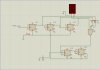
I have enclosed two diagrams produced in proteus. One of them counts 0 to 7 and then 0 to 3 and this loop goes on. It runs correctly.

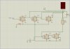
The other is supposed to count 0 to 7 and then 0 to 5 but it does not go on right. "Please help me correct it."

The final goal is to have a loop that counts 0 to 7 then 0 to 5 then 0 to 3 and then start over again. "Please kindly help me find the way to do it."

Thanks for your help in advance.
 

Attachments

  • countupto3.jpg
    countupto3.jpg
    380.7 KB · Views: 272
  • countupto5.jpg
    countupto5.jpg
    386.1 KB · Views: 283
I don't understand the purpose of U3.
I would take Q of U2A to drive CLOCK of U2B.

THEN

Use U3 to look at Q of U2B and Q of U6A. If the count = (value you want) then J=0 (K=1 all the time.) If count <> (value you want) then J=1, K=1

Looking at your 3 input NAND gate with inverters in the inputs.
Q------inverter-------NAND
This is the same as.
/Q-----------------------NAND
 
Run the five jk flip flops in line... Connect the BCD as you have ... Take the NAND_3 and connect to forth jk output
then connect to the second and third outputs ( count of 6 not 5 ) you wont see the count of six as it will be too fast.
take a normal nand (two input) and connect to the last jk and output of the third jk ( count of 4 ) again you wont see the 4 as it will reset..

Now only reset the first three... you can only reset all 5 once the sequence is completed.. Just as a teaser... Reseting jk number 4 is quite a task... But I'll let you figure it out..
 
Sorry, I am a newbie and it is difficult for me to figure out what you mean.

Run the five jk flip flops in line... Connect the BCD as you have ... Take the NAND_3 and connect to forth jk output
then connect to the second and third outputs ( count of 6 not 5 ) you wont see the count of six as it will be too fast.
take a normal nand (two input) and connect to the last jk and output of the third jk ( count of 4 ) again you wont see the 4 as it will reset..

where does the output of the nand gates you have said go? Would you please explain a little more.
 
Use U3 to look at Q of U2B and Q of U6A. If the count = (value you want) then J=0 (K=1 all the time.) If count <> (value you want) then J=1, K=1

where would the output of U3 (the nand gate with three inputs) go, according to what you have proposed?
 
It maybe we don't understand what you want to do.

I think the first "counter" should count 0,1,2,3,4,5,6,7,0,1,2,3,4..............
(there is no need for the NAND gate here)
Every time the first counter goes to 0 the second counter should advance 1. Q of counter-1 connects to Clk of counter-2
>>>If there is no NAND gate it will count 0,1,2,3,0,1,2,3....... (two flip flops)
>>>If you want it to count to a different number, connect the NAND gate to counter-2 such that when the biggest number is reached "J" of counter-2 goes low.
 
Please let me clarify my question:

I have enclosed proteus .DSN files so that you can run them if you have the software available. (You can see their schema in my previous posts)

What I want is the 7-segment to show a loop like this:
0,1,2,3,4,5,6,7,
0,1,2,3,4,5,
0,1,2,3,
0,1,2,3,4,5,6,7,
0,1,2,3,4,5,
0,1,2,3

...
and then the loop goes on again.

As you can see in the circuit "countupt03" the loop is going on right counting
0,1,2,3,4,5,6,7,
0,1,2,3,
0,1,2,3,4,5,6,7,
0,1,2,3
....
But I could not do the same for the circuit to count up to "5".

Also, I do not know how to merge these two circuits to get the desired result.
 

Attachments

  • question.zip
    29.8 KB · Views: 216
Last edited:
I thought you might work it out...

Here is how I did it...


Not pretty.. But it works.... You don't need three nand's but if you are building the circuit then its up to you..

In real life you dont want the JK inputs floating!!!
 

Attachments

  • whooah.BMP
    88.9 KB · Views: 277
Status
Not open for further replies.

Latest threads

New Articles From Microcontroller Tips

Back
Top