mstechca
New Member
I have got to admit it too!
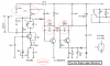
anyways. What I have going is my superregen that produces a visual output based on the incoming signal. The schematic shows the circuit without the superregen portion which connects to the input.
The problem I am having is that I cannot get the input of a 4077 XNOR gate to recognize the signal. The gate always takes the input as a logic "0".
I tried connecting the logic input to the collector of the NPN where the LED's cathode is.
If I reduce the 120K resistor, the output could be stuck at "1".
I think there is an equation with the resistor and capacitor in series that I don't know about.
I want to use my working PLL with this circuit to detect pulses.
How can I do it?
I want it so that when the transmitter outputs a logic high, I want the XNOR input to be a logic high.