Continue to Site

Welcome to our site!

Electro Tech is an online community (with over 170,000 members) who enjoy talking about and building electronic circuits, projects and gadgets. To participate you need to register. Registration is free. Click here to register now.

  • Welcome to our site! Electro Tech is an online community (with over 170,000 members) who enjoy talking about and building electronic circuits, projects and gadgets. To participate you need to register. Registration is free. Click here to register now.

Constant Current Source for PT100 circuit

Status
Not open for further replies.
btw, at present I am planning to power the whole circuit with the same SMPS.
do you think i should go for another regulator just for the bridge in case i need a 0.5 deg C resolution from my application and the range I am targetting is -20 to 200 deg C?

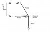
Why is your third RTD wire going to ground? That defeats the purpose of it, unless I am misunderstanding or overlooking something. It should be the zero-current connection directly from the RTD element to your voltage amplifier (as would a probe on a voltmeter sampling a voltage drop). The purpose of the 3rd wire is to eliminate at least one wire's worth of added circuit resistance. That is, in most applications I have ever seen.
 
As far as sensor lead noise is considered, is it a fair idea to have disc capacitors put up around both the lower resistances of the bridge?
I am at present using 1% resistors. Not sure if I may get the TCR type you mentioned. I shall check though.

1% resistors should be fine, and if the circuit board is in a controlled temperature environment TCR will be less critical.

As far as capacitors go, I would suggest experimenting when you breadboard your design. Expose the RTD probe leads to electromagnetic fields etc. and view the signal on a scope. Add capacitors to see the effect, if any, then test with capacitors under normal conditions. An industrial environment would definately be a candidate for filtering, especially locally at your amplifier and logic inputs. I've never breadboarded a bridge but I own and maintain several bridge designed pieces of equipment including an old Leeds and Northrup millivolt potentiometer (galvanometer)
 
I have tried to offer the same resistance to both the bridge arms.
The 3-wire RTD in my design may have 3 wire lengths equal to 50-100ft as well. Considering that each lead offers a resistance of Rw.
I have thought that the current through each arm of the bridge would traverse
5v->4k7->100e->Rw->Rw->Gnd thereby offering the bridge balance with whatever length the RTD wire has!
Please correct if I am missing something.
I shall try to experiment as far as putting capacitors is considered.

You are correct that each CURRENT CARRYING wire will have resistance that adds to the bridge, but the 3rd wire is not intended to be a current carrying wire. It is part of your differential amplifier circuit supplying measured potential to the input. The amplifier should have a very high input impedance as to not effect the bridge. The 3rd wire will be directly connected to one of the inputs, and as such is for practical description like a "probe lead" on a voltmeter to measure the voltage drop across the platinum element at the source rather than at the bridge connection. This does not actually "nullify" the resistance of the two other wires, but it more directly measures the platinum element. You will be measuring (Vrtd+wire1) rather than (Vrtd+wire1+wire2), thus your bridge will be a little more sensitive.

You should also eliminate your 100 ohm reference resistor and replace it with a precision 10 turn potentiometer, 100 ohm if you wish. I would add a precision 10 ohm resistor in series with the pot. This will allow you to calibrate your bridge.

Important note: Temperature sensor circuits at some point should be calibrated vs a known reference. The 100 ohm platinum standard is popular because ice water makes a perfect calibration standard. An aggitated mixture of ice and distilled water should be an accurate 100 ohm reference. Your probe should be submerged in the mixture and the potentiometer will be adjusted to read 0 deg C on your meter circuit. Note that water is uniform at phase change (ice-water-steam) as long as the mixture is aggitated reasonably well.

Another check can be done with boiling water, but your RTD should be very linear so that would be mostly a verification.

I do not see a reason to ground the 3rd wire. You would be better off just using a two wire RTD because the design advantage of the 3rd wire is being ignored.
 
Refer to my earlier drawing for proper connection of the 3rd wire.

EDIT.
I did some thinking about your RTD configuration and it had escaped me before but I understand now the purpose of grounding the extra lead in your scheme. I do remember seeing this in textbooks when I apprenticed as a valid technique. My apologies for not recognizing this before. I do understand that the equal lengths of wire will balance with the bridge.

The two criticisms I still have of that technique are that
1) Your ground connection will not be true ground, there will be a slight voltage drop across the ground wire which will float the circuit. This will not amount to much and the circuit will perform fine, but I do not think it is the best way.
2) Your circuit is too dependent on fixed component values, IMHO. With the unknown variable that exposed, long probe leads creates, I would be concerned with the effect of temperature, etc on the leads. I am sure you will be incorporating a method of calibration somewhere in the circuit, perhaps in the amplifier stage or in the A/D circuit, but I think the circuit should be balanced at the source (the bridge). This does not preclude further manipulation of the signal at later stages, but it establishes a baseline from which to work. This is why I mentioned an adjustment potentiometer.

BTW, if you are certain of using the grounded wire technique, I still think a potentiometer for calibration is advised.
 
Last edited:
Thanks a lot for the detailed explanation. I have read it all but feel a little confused over something you mentioned under the EDIT.
1. How will there be a voltage drop across ground?
2. I fully agree with you about the potentiometer use. I shall be following the same

One thing I wish to mention is that the lengths of the RTD will not be known to the circuit and to me also as a designer. (they vary with site and installation)
So, what value pot (10e + 100e as of now) would be sufficient to compensate for the actual wire resistances?

If I connect the third RTD wire directly to AMP, as shown in the schematic you posted, will it's length (and so the resistance) will ever matter in the measurement?

I took the 3rd wire grounding approach just to compensate for the Unknown lengths that RTD wires may have in the field/on application site.

I am using AD623 INAmp as stated earlier that offers an input impedance of 2Gohm // 2pf
Do I need to add anything else in the voltage input path of the amplifier from the bridge?
Or directly connecting the bridge centers to INV and NonINV terminals would do?

About calibrating my circuit, I am having a mangenin resistance of exactly 100e accurate to 6 digits which I am thinking of connecting in place of the RTD and adjust the zero. (zero adjust with the 10e pot you suggested) Please suggest if I am missing anything.
 
Last edited:
https://www.electro-tech-online.com/attachments/cld-jpg.35363/
I favorite very near constant current is the CRD made with a jfet, the current out goes through a resistor and is fed back to the gate. the above mentioned thread was for 1.5 ma current
1.924K ohm gave me 1.43 ma at 10 volts on the following drawing.
kinarfi
 

Attachments

  • CLD.jpg
    CLD.jpg
    4.5 KB · Views: 579
Last edited:
"How will there be a voltage drop across ground?"...SEE ATTACHMENT

The resistance of the 3rd wire is the same as the resistance of the other leads. I am correct in that you are connecting this wire to ground? I am assuming not earth ground though, because you are using a SMPS correct? SMPS is a floating voltage source, the output is isolated, so Earth ground will not be proper. Your ground lead would need to be routed with the other rtd wires back to the circuit board to common on the power supply. The length of that wire would be Rwire and thus your bridge would be Rwire above ground. No big deal but not ideal.

"So, what value pot (10e + 100e as of now) would be sufficient to compensate for the actual wire resistances?"

I think this will do. Consider your longest possible wire distance and calculate R/meter for the appropriate gauge. At most a few ohms, so 10e+100e should be enough.

"If I connect the third RTD wire directly to AMP, as shown in the schematic you posted, will it's length (and so the resistance) will ever matter in the measurement?"

Very little as long as your amplifier inputs are very high impedance. If not, use current limiting resistors at the inputs, 100k to 1 Meg...Your amplifier inputs are voltage signals with very little current, therefore no voltage drop in the connections. I do not mean that the 3rd wire should be directly connected wire-to-amp. I mean there should be a direct connection via circuit board trace with no active components. so, rtd-wire-trace-amp. Of course, if you need higher impedance for the amp inputs it would be rtd-wire-trace-limiting resistor-amp.

Ah, your next paragraphs says very high input impedance. GOOD. No current limiting required.

Your precision resistance reference is perfect for calibrating zero as long as the connection is made INCLUDING the long leads. Your reference (probe simulator, decade box, etc) should be connected ONLY in place of the platinum element, so the connection should be made remotely, this is because the wires will be an OPERATIONAL circuit resistance so they must be included when calibrating. Your reference ONLY REPLACES THE 100 ohm element, not element plus wire.

I still suggest that an icewater validation be performed on the COMPLETE FUNCTIONAL CIRCUIT as a full function test.
 

Attachments

  • rwire.jpg
    rwire.jpg
    20.4 KB · Views: 1,314
Last edited:
gr8 to know all this from you. I appreciate your support.
I understood the floating load from the last schematic.
One thing, what process is to be followed for your original RTD connection schematic (where 3rd wire connected to amp input)?
As I said earlier, the field wire length will vary for RTD so I am not sure if my lab calibrartion will ever be exact/sufficient once I roll out the product to field/site?
No matter which way I connect the RTD in the bridge, i think.
Any thoughts please.

Also, you may have a look at: https://www.electro-tech-online.com/custompdfs/2009/11/70600di.pdf
There is a circuit of PT100 in this file where 2 of the 3-wires carry current. This is a little deviating from what you have explained earlier.
 
Last edited:
FYI that is not a wheatstone bridge circuit in your PDF. In fact it confirms what I said earlier about constant current sources being for non-bridge RTD applications.

My earlier comment...."In fact, a constant current source eliminates the need for a bridge altogether, because the voltage drop across the RTD in series with a single resistor would suffice as long as no current variability occurs."

Typically, this is where 4-wire RTDs are used, but this DOES NOT preclude a 2 wire or 3 wire from being used in a non-wheatstone constant current design. As you should be aware, there are often many ways of accomplishing the same thing, many solutions to the same problem. It is just a matter of design choices.

In any case, in the other explanation I made for a wheatstone 3-wire circuit, only two wires carry current, the 3rd wire carries voltage only, as long as the amplifier input is very high impedance.

If you are modeling after the design you just linked to, there is no need in using the bridge. Bridges are definately still utilized in instrumentation circuits, but more and more with digital temperature circuits the type design you linked to are being used. The reason being because wheatstone bridge circuits do not DIRECTLY utilize the ohmic linearity of the RTD. A platinum RTD has a linear 0.385 ohm per degree C calibration curve. The differential voltage your amplifier will be seeing will be a much smaller (yet proportional) signal.

The constant current can be set up so that a voltage drop-ohmic change measurement is more directly made. A constant current component will be in series with the RTD and will sense changes in the RTD and adjust its own ohmic value to maintain the constant current. As the RTD reduces, the CC source will increase and vice-versa. This creates a linear, predictable voltage drop change across the RTD that can be measured by the amplifier.

The 4 wire RTD is ideally suited for this, because BOTH extra wires act as voltmeter leads, directly measuring the platinum bulb at its terminals. The alternative is measuring the bulb plus all the wire as in the 2-wire method. This disrupts that near perfect linearity of the RTD because wire resistance is less predictable.

A 3 wire setup is a compromise but can still be very effective in a constant current design if one of your amplifier inputs is at ground potential.

I just googled a pretty good explanation here:
**broken link removed**
 
I apologise for diverting the discussion. I should have understood the absence of Wheatstone bridge in the design I pointed out.
I shall have a look at the googled link you posted. Thank you so much.

I actually have made up my mind to kind of continue the design with the 3-wire RTD and wheatstone bridge way. [Some parts availability reason also involved]

Do you have any explanation for the resistance of the voltmeter lead wire (3rd wire) of RTD in case it's length is variable.
By variable i mean it can be dynamic per piece of the product.

Also, as i asked about the one time compensation for zero with some 'x' length of RTD wires considered. What if that changes to any 'y' value later?
The calibration done will be deemed erratic.. am I right?

Is there any elegant way for the calibration?
I may be sounding foolish here but need to know.

Thank you so much ke5frf
 
I had a look at the weblink you sent. Looking at the 3-wire configurations,
"You make this connection" and at the alternative 3-wire config, "Rd (user supplied)"
Figure-4
Can you explain it a bit please?
 
I uploaded a drawing to explain the common-mode rejection operation of the IC circuit in your PDF. You can see how there are two reference RTDs built into the chip, with 2 constant current sources for both branches of the circuit. It is very similar in a way to a bridge circuit, except that in a bridge the balance is achieved by the bridge itself. The CC circuit doesn't care or rely on balance, but does succeed in eliminating the influence of all resistances except the variable of interest i.e. the RTD probe itself. You might call a common mode rejection design an "ALL THINGS BEING EQUAL" circuit. The internal RTDs are simply references that help stabilize the two branches of the circuit, negating temperature influences on the integrated circuit that might occur, if I understand it correctly anyway.

I hope this helps you understand the difference between a bridge design and the constant current design concept.
 

Attachments

  • rtdchip.jpg
    rtdchip.jpg
    41.2 KB · Views: 1,221
perfect.... i got the explanation. Thanks mate.
So, if my design is now not involving any current sources but the bridge, then the resistors being in cloce match will decide the accuracy of the desing.
Am i right?

Other story is the input impedance of my amplifier being very high will not need any componets between the amplifier terminal and the rtd voltmeter probe lead.. right?

What is your feeling about the error that may be there (if it is) in my design due to the lengths of the RTD 3-wires if the length is variable... over the one that the calibration is done for?
 
"Do you have any explanation for the resistance of the voltmeter lead wire (3rd wire) of RTD in case it's length is variable.
By variable i mean it can be dynamic per piece of the product."

I don't know any better way of explaining this. If you use the 3-wire design that I suggest is best, the 3rd lead will not be a current carrying lead. It will only be a voltage sensing lead. The high input impedance of your amplifier will prevent significant current flow. In this way it will be like the input of an FET device in a digital circuit, not loading the gate in any way. You do know how FETs are voltage controlled devices? The same principle applies. I should think your differential amplifier should be a CMOS device ideally, and judging by the input impedance you described it likely is. I haven't looked up any datasheets here BTW.

There will be little to no current flowing between the sense voltage at the RTD and the corresponding amplifier input, so resistance will be a non issue. Please tell me if you understand this? If you do not, consider that when designing an FET transistor gate input, a designer is free to choose among pull up or pull down resistor values with a lot of liberty. The proper switching of the FET device will occur whether the impedance is 100k or 10meg, the only variability becomes the speed at which it switches. Here, the only variability that input impedance has on your amplifier is its responsiveness, the speed at which it responds to changes in the RTD. Whether your lead impedance is 1 ohm or 10 ohms, there will be for practical purposes NO noticeable difference in response time. The value is too low to be of any consequence.

"Also, as i asked about the one time compensation for zero with some 'x' length of RTD wires considered. What if that changes to any 'y' value later?
The calibration done will be deemed erratic.. am I right?"

In a steady state implimentation of your circuit, there should be no changes in wire length. If, for some reason, a shorter probe wire length became neccessary, then a recalibration would be required. I have worked with temperature control circuits 5 days a week for the past 10 years. Recalibrations are the nature of the beast and always have been, even with very good designs. RTDs rarely fail, but as they age, especially if the environment and temperatures are harsh, slight "biases" occur that have to be eliminated. In modern digital electronic equipment, these corrections are often done digitally, corrections made in the calculations done by microprocessors.

I do not know how involved you intend your design to be, but this would be how variabilities are typically mitigated in modern circuits. You can do this only assuming that the linearity of the RTD is not a changing variable. The bias usually corrects across the calibration curve of the RTD equally. In fact, very good designs permit multiple corrections for temperature ranges as well (multipoint calibration), adjusting the calibration curve to suit your needs and mitigate any discrepencies in the response of the probe at any temperature.
 
I had a look at the weblink you sent. Looking at the 3-wire configurations,
"You make this connection" and at the alternative 3-wire config, "Rd (user supplied)"
Figure-4
Can you explain it a bit please?

Well, that would be an external resistor added in series with the constant current excitation of this particular module. Probably for current limiting, setting a maximum current, perhaps in case of a short. It would also probably be there to mitigate the heat effects of circuit current. RTDs self heat to a certain degree if too much current is used to excite them. Remember, they are only 100 ohm devices and if the voltage applied becomes too great the current might become excessive causing self heating or even damage to the circuit. Be aware that each integrated circuit you look at will have its own peculiarities of design. Also, this again is a constant current circuit so design considerations will be different from your bridge circuit.
 
ah.. now I got it all, I think.
I shall be calibrating the circuit to the known length and later leave some scope in the processor software if needed.
Let me try it sometime in nxt week with the approach your initial schematic showed. Wish me luck. I am really grateful to you for all the painful efforts you took to stand by me. I shall keep you posted with the design results. I hope you would help in future on this design if need be!

BTW, I had a relook at the IN Amp AD623A datsheet I have. It apears that the input signal is applied across a PNP transistors base-emitter (N-P) junction. Hence, it offers a very high input impedance. My thought. :)
 
Last edited:
perfect.... i got the explanation. Thanks mate.
So, if my design is now not involving any current sources but the bridge, then the resistors being in cloce match will decide the accuracy of the desing.
Am i right?
Yes, other than your calibration resistor (potentiometer) and perhaps a small series resistor associated with it, the other two resistors should be precisely matched with exceptional temperature coefficient. And with the potentiometer calibrated to the RTD at 0 degrees, or with a probe simulator, the potentiometer will balance with the RTD and wire resistance will be accounted for as well.

Other story is the input impedance of my amplifier being very high will not need any componets between the amplifier terminal and the rtd voltmeter probe lead.. right?
I would think not, unless perhaps you want to short protect it some kind of way with a current limiting resistor, perhaps 1kohm of the top of my head. It should have no negative effect either way, except a slight, slight delay in the responsiveness of the probe.[/quote]

What is your feeling about the error that may be there (if it is) in my design due to the lengths of the RTD 3-wires if the length is variable... over the one that the calibration is done for?

Again, I keep harping on this, I don't advise trying to design a perfectly balanced bridge. All resistors should be precision components for stability purposes, but I do not think you can reproduceably manufacture multiple circuits with varying probe lengths and completely rely on building a perfectly balanced bridge without the ability to calibrate it. You will run into all sorts of problems and become very frustrated. Without designing in some sort of calibration mechanism, I doubt seriously that your circuit would even read 0 degrees with a perfectly balanced bridge. It would take a lot of trial and error in the A/D, amplifier, and microprocessor level, and even then it won't be exactly reproduceable when your next circuit has twice the probe length.

The solution is the variable resistor on the bridge, and calculating the range you will need out of the potentiometer, and selecting a suitable series resistance to go with it. I suggest a 10 ohm fixed precision resistor and a 100 ohm pot because the 10 ohms gives you headroom, the pot can be adjusted to 90 ohms giving you balance at 0 degrees. The 10 ohms would accomodate most wire length variabilities. But perhaps a 20 ohm resistor would be better. This really is something that can't be entirely figured out in this discussion and mght even require some trial and error on the breadboard.

OK, I have just about shared all I know or understand here on this topic. I work with RTDs, but my technical profession is more along the repair and calibration of industrial/laboratory test equipment that involves temperature measurement and control. I only occasionally design circuits for my work, and where temperature control is involved I always purchase DIN PID temperature controllers suitable for the application, with only external circuits, relays, valves, actuators, heat elements, and probe selection being my design considerations.

I have offered all I know. From here out I hope someone else can help guide you if I can't answer questions.
 
ah.. now I got it all, I think.
I shall be calibrating the circuit to the known length and later leave some scope in the processor software if needed.
Let me try it sometime in nxt week with the approach your initial schematic showed. Wish me luck. I am really grateful to you for all the painful efforts you took to stand by me. I shall keep you posted with the design results. I hope you would help in future on this design if need be!

BTW, I had a relook at the IN Amp AD623A datsheet I have. It apears that the input signal is applied across a PNP transistors base-emitter (N-P) junction. Hence, it offers a very high input impedance. My thought. :)

Well, this is where me not being a professional or even really good amateur designer gets in the way. That instrumentation amplifier is a TTL device as far as I can see, and I see no internal current limiting at the inputs. Granted, the differential voltage that will be presented to the inputs will be in the millivolts, but voltage from ground may or may not be so. I'm not sure how a TTL amplifier could have 2 G-Ohm input impedance other than the impedance BETWEEN the two inputs. The impedance with respect to ground will surely not be 2G. But this is where I don't trust my knowledge and rely on instincts. My instincts would tell me that a CMOS amplifier would be a better choice, or else I would have to consult the manufacturer for specific answers on the chip. I would not want to take a chance that my amplifier would load down my bridge circuit in any way. Obviously they are designed for instrumentation applications, so logically I would have to assume the amplifiers are designed to not interfere with the bridge. Maybe someone with more technical expertise on the input impedance of these amplifiers can shed the light you need.
 
It doesn't really describe it on the datasheet, but there is input buffering going on to allow for the high input impedance on that Iamp. That is a design consideration I didn't think of. Some things are just assumed, and I neglected to remember that Iamps by definition are designed to be high impedance, non loading circuits.
 
Status
Not open for further replies.

Latest threads

New Articles From Microcontroller Tips

Back
Top