I've been repairing a Crest Audio CA9.
Crest have very usefully posted the schematic here:-
https://www.crestaudio.com/media/schematics/ca_schematic_set1.pdf
In the main amplifier, Q22 had blown, resulting in several of the resistors going up in smoke. I changed all of them and Q21 and Q22.
It seemed to be working, until I put it all back together, when R139 burned out. I realised that the tab of Q22 was shorting to the heatsink, which only mattered when the heatsink was earthed.
Anyhow I changed R139 but the amplifier was oscillating at MHz frequencies, only at the positive peak of each cycle.
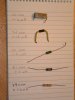
Eventually, I fixed it by changing R146 and R147 from wirewound to carbon film resistors.
(https://uk.farnell.com/1903870 to https://uk.farnell.com/9338039)
It seems that something changed when R139 blew, but I have no idea what. It also seems that the inductance of R146/R147 is very important. I was surprised how critical it was.
Crest have very usefully posted the schematic here:-
https://www.crestaudio.com/media/schematics/ca_schematic_set1.pdf
In the main amplifier, Q22 had blown, resulting in several of the resistors going up in smoke. I changed all of them and Q21 and Q22.
It seemed to be working, until I put it all back together, when R139 burned out. I realised that the tab of Q22 was shorting to the heatsink, which only mattered when the heatsink was earthed.
Anyhow I changed R139 but the amplifier was oscillating at MHz frequencies, only at the positive peak of each cycle.
Eventually, I fixed it by changing R146 and R147 from wirewound to carbon film resistors.
(https://uk.farnell.com/1903870 to https://uk.farnell.com/9338039)
It seems that something changed when R139 blew, but I have no idea what. It also seems that the inductance of R146/R147 is very important. I was surprised how critical it was.