Basically and messing with a top of the line food blender.....lol.. Rather simple system other than they use a PIC to ramp up and PWM the output for speed control, timers, etc. I bought it broke and was able to find most of the issues. Owner reported spontaneous stops in a cycle.
What I found was a 5V reg and a fast switching transistor in TO-220 packages that appeared to be killed by vibration. The pins were cracked and one component had come off. Before the repair, the machine would indicate "no zero crossing, alarm", now with the parts repaired, the LCD lights up and it knows it name and serial number, has all memory functions, etc.
Problem is when "go" is commanded to run the motor, it obviously does not do a think, then it will error out with "over load". I know it is showing overload only because it has a tach on the motor and assumes it is stalled. My assumption is this problem must be towards the very end of the output side since the PIC does not indicated any errors. I am confident that if the motor was spinning, there would be a tach input back to the machine and all would be good..
In the output stage, the PIC appears to fire an MOC3052 optoisolator which in turn runs 2 SCRs (S6025L). This circuit is NOT dc rectified. There is only a small PS for the 5V logic power. I will admit that I lack the education to know enough about this thing. I am trying to determine what I should be looking for? My gut is telling me to just replace or test the MOC3052. I just have a hard time believing that both of the SCRs are toast.
I am also NOT convinced ANY of these components are bad. IME, when I find a component I think is bad, I end up bench testing it good which means there is some sort of leakage or something else over my head...
There is also an MOV that seems to be parallel to the output that looks fine. IME, when MOVs fail, you know it.... There are a few other chips and such on the board but the output looks rather simple. There are a few resistors in the output stage but I have a hard time believing they are bad.
Is there a good way to test this MOC3052 in circuit to see if it is outputting? My guess is no but probably is not getting what it needs to fire IMO..
By the way, NO, I cannot get a circuit diagram (that would be GREAT) and the OEM will not help at all other than charge near new price for just the board. I am confident all logic circuits are fine and there is something wrong with the output stage only.
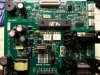
EDIT: I have uploaded a pic of the board in question. The MOC3052 is the 6pin dip chip below the PIC on the right. You can see the 2 SCRs on the bottom right on their heat sinks. Just thought it might help for someone to kind of see what I was working on. I realize no one will be able to precisely decide my problem. I am only looking for general information regarding failures of PWM circuits, etc.
What I found was a 5V reg and a fast switching transistor in TO-220 packages that appeared to be killed by vibration. The pins were cracked and one component had come off. Before the repair, the machine would indicate "no zero crossing, alarm", now with the parts repaired, the LCD lights up and it knows it name and serial number, has all memory functions, etc.
Problem is when "go" is commanded to run the motor, it obviously does not do a think, then it will error out with "over load". I know it is showing overload only because it has a tach on the motor and assumes it is stalled. My assumption is this problem must be towards the very end of the output side since the PIC does not indicated any errors. I am confident that if the motor was spinning, there would be a tach input back to the machine and all would be good..
In the output stage, the PIC appears to fire an MOC3052 optoisolator which in turn runs 2 SCRs (S6025L). This circuit is NOT dc rectified. There is only a small PS for the 5V logic power. I will admit that I lack the education to know enough about this thing. I am trying to determine what I should be looking for? My gut is telling me to just replace or test the MOC3052. I just have a hard time believing that both of the SCRs are toast.
I am also NOT convinced ANY of these components are bad. IME, when I find a component I think is bad, I end up bench testing it good which means there is some sort of leakage or something else over my head...
There is also an MOV that seems to be parallel to the output that looks fine. IME, when MOVs fail, you know it.... There are a few other chips and such on the board but the output looks rather simple. There are a few resistors in the output stage but I have a hard time believing they are bad.
Is there a good way to test this MOC3052 in circuit to see if it is outputting? My guess is no but probably is not getting what it needs to fire IMO..
By the way, NO, I cannot get a circuit diagram (that would be GREAT) and the OEM will not help at all other than charge near new price for just the board. I am confident all logic circuits are fine and there is something wrong with the output stage only.
EDIT: I have uploaded a pic of the board in question. The MOC3052 is the 6pin dip chip below the PIC on the right. You can see the 2 SCRs on the bottom right on their heat sinks. Just thought it might help for someone to kind of see what I was working on. I realize no one will be able to precisely decide my problem. I am only looking for general information regarding failures of PWM circuits, etc.
Attachments
Last edited:
