1.- I am planning to use the 16F870 microcontroller to acquiere analoge signals, but I really do not know what are the voltage limits, I mean if I have a have an analog singal at a frequency of 60 Hz what are the maximun Vpp the uC can support.
According to some examples I have found on the web, the maximum voltage is 5 volts as upper limit and 0 volts as the lower limit and this signal varies by a potentiometer.
2.- Thanks a lot for your comments Nigel. I found useful the tutorial I will begin to program as soon as I have resolver my electronic designs and that's another history.
By the way, I want to sample an analog voltage at a frequency of 60Hz
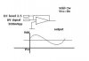
the amplitud can vary from 100mV to 8V. I think I can use an opamp configuration to reduce the high voltage, does one pin can sample the incoming signal mounted on the DC level, isn't it?.
However this signal comes from a differential transformer, do you think I can put my analog signal so to say 100mV, into a DC level between 0 to 5 volts in order to sample it.
then when I want to sample high AC voltage level I could make drop its amplitud to put it in a dc level and then sampling it.
Am I right?
Does anyone can help me with these questions
Thanks a lot
According to some examples I have found on the web, the maximum voltage is 5 volts as upper limit and 0 volts as the lower limit and this signal varies by a potentiometer.
2.- Thanks a lot for your comments Nigel. I found useful the tutorial I will begin to program as soon as I have resolver my electronic designs and that's another history.
By the way, I want to sample an analog voltage at a frequency of 60Hz
the amplitud can vary from 100mV to 8V. I think I can use an opamp configuration to reduce the high voltage, does one pin can sample the incoming signal mounted on the DC level, isn't it?.
However this signal comes from a differential transformer, do you think I can put my analog signal so to say 100mV, into a DC level between 0 to 5 volts in order to sample it.
then when I want to sample high AC voltage level I could make drop its amplitud to put it in a dc level and then sampling it.
Am I right?
Does anyone can help me with these questions
Thanks a lot