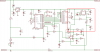
I was building a simple wattmeter using the schematic as shown here
And the ASM code for PIC16F88 here to drive the JHD162A LCD as well.
(The code is on 4 bits HD44780, but is compatible with KS0066 driver used here.)
However after I'd built the circuit, I found that LCD shows nothing.
And I wonder if I had done something wrong on my code or what, or maybe thay said I need some kind of driver "wake-up" for the LCD module?
Thanks if you can help.
")