Electronic Projects, forums and more.

Go Back   Electronic Circuits Projects Diagrams Free > Electronics Categories > Micro Controllers


Micro Controllers Discuss all aspects of micro controllers - building them, coding them, etc. All controllers are welcome - PIC, BASIC, Z8 Encore!, etc.

Reply
 
LinkBack Thread Tools Display Modes
Old 10th October 2007, 03:57 AM   (permalink)
Arrow Programmable Third Brake Light Flasher - PIC12F629

Here is another Kindergarten project of mine. It’s called programmable third brake light flasher. Looks like simple but need to think in all round.

Operation
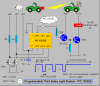
When brake is applied the circuit will flashes the third brake light couple of times & stays continuously on until the driver releases the brake. This will make other drivers attention due to the flashing effect with a safety manner.
Number of flashes, flash on time and flash off time can be adjust by the user with the two buttons.

Here nothing is illegal so I didn’t get a problem. Also this is not for commercial I did just for fun.


This circuit designed for LED third brake lights & not for incandescent (filament) third brake lights.

I got several problems when calculating the pulse delay for incandescent bulbs. Because these bulbs take time to switch on & off. They won’t accept high speed switching. It’s easy to calculate a long delay but if the PULSE OFF DELAY time is too long in a traffic condition it will meet some problems. If the pulse delay time too short it won’t show you the blinking effect because of poor turning on time with these bulbs. So I escaped from incandescent bulbs. Modern all automobile lighting systems using LED’s. So I also shifted to high speed LED’s.

The delays are calculated to the best timing parameters. Can use all this calculated delays in the table without any problem.

The Zip file contains how to adjust routine.
Attached Images
File Type: png BL.PNG (34.1 KB, 17 views)
Attached Files
File Type: zip How to Adjust.zip (34.7 KB, 22 views)
__________________
Gayan

My Website
http://gsmicro.blogspot.com/
Gayan Soyza is offline  
Old 10th October 2007, 04:17 AM   (permalink)
Default

Nice graphics. It would be funny if the 12F629 was thinking it was 12F675 or a 18F series chip. Dream on little PIC.
On a more serious note, I think your off time of 0.04s is a little too short but since it will be adjustable it is probably not an issue.
Kudos on the professional presentation!
__________________
--- The days of the digital watch are numbered. ---
kchriste is offline  
Old 10th October 2007, 04:30 AM   (permalink)
Default

Thanks Kchristie

I tested on many delays. It took me lot of time to calculate what’s the best delay range.

Also with some of the above delays bulb doesn’t have time go fully off it looks like dimming if you reduced to the minimum delay with some bulbs. The maximum off delay is upto 0.05 seconds adjustable so can see the bulb going fully off. So I got advantage from it.
__________________
Gayan

My Website
http://gsmicro.blogspot.com/

Last edited by Gayan Soyza; 10th October 2007 at 04:37 AM.
Gayan Soyza is offline  
Old 10th October 2007, 04:29 PM   (permalink)
Default

Hi,
Really nice graphics
Can I know what is the purpose of the 1 khm: resistor?
__________________
Superman returns..
bananasiong is offline  
Old 10th October 2007, 04:37 PM   (permalink)
Default

It's to ensure the TIP41 turns off fully, otherwise any slight leakage in the driver might keep it switched on.

It's good practice to include such resistors.
__________________
PIC programmer software, and PIC Tutorials at:
http://www.winpicprog.co.uk
Nigel Goodwin is online now  
Old 10th October 2007, 05:38 PM   (permalink)
Default

This resistor is needed for what type of configuration? Emitter drives base type? Or for those common emitter type switch?
Can I know where the leakage from that causing the transistor for keeping on? I don't see how the TIP41 is turned on if the 2N2222 is not turned on.

Thanks.
__________________
Superman returns..
bananasiong is offline  
Old 10th October 2007, 07:53 PM   (permalink)
Default

"kindergarten"? Is this going on a real car or a Power Wheels Hummer? Unless you mean because it's a basic circuit. Either way, this would be a good idea for one when it is running. Good safety gear. But I would rather just attach a 30' cable from the kiddies vehicle to the house lol.

I have seen some modded brakes lights on youtube. One guy has a full width brake light on the trunk, and imitates a cylon visor. But I am not sure if they are still legal in the US as long as they do not flash. But you can try that kind of thing if you get a bigger PIC. And a load of LED's from http://alan-parekh.vstore.ca/
Ambient is offline  
Old 10th October 2007, 10:08 PM   (permalink)
Default

Quote:
Originally Posted by bananasiong
I don't see how the TIP41 is turned on if the 2N2222 is not turned on.
Like I said in the previous post, if there's any slight leakage in the driver (the 2N2222) it might switch the TIP41 on - at least partially.
__________________
PIC programmer software, and PIC Tutorials at:
http://www.winpicprog.co.uk
Nigel Goodwin is online now  
Old 11th October 2007, 04:49 AM   (permalink)
Default

Really nice work!

Last edited by Suraj143; 11th October 2007 at 04:52 AM.
Suraj143 is offline  
Old 11th October 2007, 04:59 AM   (permalink)
Default

Hi bananasiong

Nigel already points outs what’s the purpose of that 1k resister. It’s to ensure that the power transistor is fully off.

Some addition points

The 1k resistor on the base will have an effect on the current required by the base to turn the transistor on. So it increases the required base current. If no resister it will turn the transistor on with a few uA. Most of the current delivered into the base is lost in the biasing network. Darlington pairs have built in these resisters.

Also note that when the load increases the transistor gets hot. Sometimes it tries to get latch due to heat so the 1k resistor turns off the power transistor even if heat tries to keep it turned on.
__________________
Gayan

My Website
http://gsmicro.blogspot.com/
Gayan Soyza is offline  
Old 11th October 2007, 05:01 AM   (permalink)
Default

Quote:
Originally Posted by Ambient
I have seen some modded brakes lights on youtube. One guy has a full width brake light on the trunk, and imitates a cylon visor. But I am not sure if they are still legal in the US as long as they do not flash. But you can try that kind of thing if you get a bigger PIC. And a load of LED's from http://alan-parekh.vstore.ca/
Hi Ambient your link is not working.I want to see that I cannot wait anymore
__________________
Gayan

My Website
http://gsmicro.blogspot.com/
Gayan Soyza is offline  
Old 11th October 2007, 02:26 PM   (permalink)
Default

Quote:
Originally Posted by Nigel Goodwin
Like I said in the previous post, if there's any slight leakage in the driver (the 2N2222) it might switch the TIP41 on - at least partially.
Don't worry about leakage. The circuit is good for one off operation only as the TIP41 BE junction will burnt out immediately when the 2N2222 turns ON.
__________________
L.Chung
eblc1388 is offline  
Old 11th October 2007, 03:42 PM   (permalink)
Default

Quote:
Originally Posted by eblc1388
Don't worry about leakage. The circuit is good for one off operation only as the TIP41 BE junction will burnt out immediately when the 2N2222 turns ON.
Good point, the diagram is missing a resistor in the emitter of the 2N2222.
__________________
PIC programmer software, and PIC Tutorials at:
http://www.winpicprog.co.uk
Nigel Goodwin is online now  
Old 12th October 2007, 01:35 AM   (permalink)
Default

Quote:
Originally Posted by eblc1388
Don't worry about leakage. The circuit is good for one off operation only as the TIP41 BE junction will burnt out immediately when the 2N2222 turns ON.
Is that because of the emtter of 2N2222 is not current limited? What if the collector of 2N2222 connected to the collector of the TIP41 to form darlington?
__________________
Superman returns..
bananasiong is offline  
Old 12th October 2007, 03:57 AM   (permalink)
Default

Doesn’t the inbuilt collector & emitter diodes of 2N 2222 helps to drop down the voltage below 5V? & also data sheet shows TIP41’s maximum base current is supports to a bigger value.

Now already two weeks continuously running in a damn hot environment no more problems occurred.

Anyway I like your ideas thanks for that guys.
__________________
Gayan

My Website
http://gsmicro.blogspot.com/
Gayan Soyza is offline  
Reply

Bookmarks

Thread Tools
Display Modes


Similar Threads
Title Starter Forum Replies Latest
Triac light bulb flasher ElectroMaster Electronic Projects 17 30th July 2008 04:20 PM
Pulsing Third Brake LIght Problem. ( whats wrong with this cct ? ) pasanlaksiri General Electronics Chat 4 19th September 2007 07:07 PM
Need Help Designing LED Tail/Brake Light ledsales Electronic Projects Design/Ideas/Reviews 28 23rd May 2007 07:40 AM
MC Brake Light - Circuit Help Needed I-See Electronic Projects Design/Ideas/Reviews 4 16th February 2007 03:28 AM
brake light/ turn signal andrew8485 Electronic Projects Design/Ideas/Reviews 13 11th November 2003 01:49 AM


All times are GMT. The time now is 09:40 PM.


Electronic Circuits  |  Learning Electronics
Powered by vBulletin® Version 3.7.0
Copyright ©2000 - 2008, Jelsoft Enterprises Ltd.

eXTReMe Tracker