Mike - K8LH
Well-Known Member
Here's another relatively simple 8-channel or 16-channel 'hardware' Servo controller method which utilizes the CCP PWM module and one or two 74HC238 decoder ICs (inspired by contributions over at Forum.Microchip). It's relatively low overhead, interrupt tolerant, and should provide 250-nsec pulse width resolution with zero Servo period jitter and zero pulse width jitter.
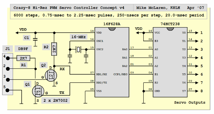
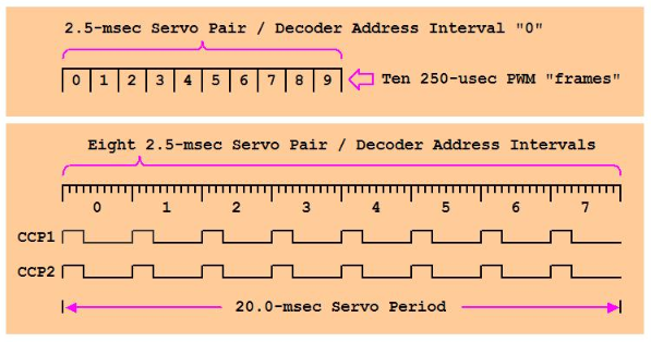
Using a 16-MHz oscillator the PWM module is setup with a 250-usec period (prescaler 4:1) and there will be 80 of these PWM periods or "frames" within each 20-msec Servo period.
I decided to use ten "frames" which form 2500-usec Servo Pair "intervals" equally spaced across the 20-msec Servo period. I also limit each Servo pulse width value to 2250-usecs max' to insure that the 10th PWM "frame" in each Servo pair "interval" will always have a 0% duty cycle where it'll be safe to update the address lines on the 74HC238 decoder IC.
Here's the algorithm in C18 for a 16 channel controller using 74HC238's connected to CCP1 and CCP2 (RB0..RB2 pins driving the address lines on both 74HC238 ICs);
Code:
/*                                                               *
 *  array1 and array2 elements hold Servo pulse width values     *
 *  ranging from 3000..9000 in 250-nsec 'ticks' representing     *
 *  pulse width ranges of 750-usecs to 2250-usecs                *
 *                                                               */
static unsigned int array1 [] = { 6000, 6000, 6000, 6000,
                                  6000, 6000, 6000, 6000 };
static unsigned int array2 [] = { 6000, 6000, 6000, 6000,
                                  6000, 6000, 6000, 6000 };

/*****************************************************************
 *  K8LH Crazy-16 Hi-Rez 'PWM' Servo Algorithm Interrupt Driver  *
 *****************************************************************/
#pragma interrupt isr_hi

void isr_hi ()
{ if(PIR1bits.TMR2IF)
  { PIR1bits.TMR2IF = 0;
   /*                                                            *
    *  setup decoder address lines and work variables for the    *
    *  next servo pair during the 10th and final frame of the    *
    *  current servo pair interval (the 10th frame always has    *
    *  a 0% duty cycle so the 74HC238 outputs are all off and    *
    *  it's safe to change the address lines)                    *
    *                                                            */
    if(frame == 10)                 // # FRAMES_PER_SERVO_PAIR_INTERVAL
    {
      frame = 0;
      servo_select %= 8;            // % NUMBER_OF_SERVO_PAIRS
      pulse1 = array1[servo_select];
      pulse2 = array2[servo_select];
      PORTB = (PORTB & 0b11111000) | servo_select;
      servo_select++;
    }
    frame++;                        // bump for next interrupt

   /**************************************************************
    *  setup CCP1 PWM duty cycle for next 250-usec PWM 'frame'   *
    *                                                            */
    if(pulse1 > 1000)               // if pulse1 > 250-usecs
    {
      CCPR1L = 250;                 // do a 100% duty cycle frame
      pulse1 -= 1000;               // subtract 250-usecs
    }
    else                            // do a variable or 0% frame
    {
      CCP1CONbits.CCP1Y = (pulse1 & 1);
      CCP1CONbits.CCP1X = (pulse1 & 2);
      CCPR1L = (pulse1 >>= 2);
      pulse1 = 0;
    }

   /**************************************************************
    *  setup CCP2 PWM duty cycle for next 250-usec PWM 'frame'   *
    *                                                            */
    if(pulse2 > 1000)               // if pulse2 > 250-usecs
    {
      CCPR2L = 250;
      pulse2 -= 1000;
    }
    else
    {
      CCP2CONbits.CCP2Y = (pulse1 & 1);
      CCP2CONbits.CCP2X = (pulse1 & 2);
      CCPR2L = (pulse2 >>= 2);
      pulse2 = 0;
    }
  }
}
Attachments


Last edited:
