Continue to Site

Welcome to our site!

Electro Tech is an online community (with over 170,000 members) who enjoy talking about and building electronic circuits, projects and gadgets. To participate you need to register. Registration is free. Click here to register now.

  • Welcome to our site! Electro Tech is an online community (with over 170,000 members) who enjoy talking about and building electronic circuits, projects and gadgets. To participate you need to register. Registration is free. Click here to register now.

555 monostable circuit to trigger solenoid valves questions

Status
Not open for further replies.

rizla90

New Member
Hello everyone,
Well i posted a similar circuit in another topic but a lot has changed in the design. So here is a brief story of what i am doing, actually i am in a project where i have to design a circuit which can be used to trigger solenoid valves for the airbags in the car, so i need a circuit with a time range of 0 to 1 seconds. Also the valves chosen are 12 V, 0.5 A and can go up to the maximum speed of 200 milisecond. In my group meeting it was decided to use a monostable 555 circuit to trigger valves as they need some sort of time regulation because it is something like that you press a button and an airbag go will off instantly and that car would be a demonstrator only!
So I have made a schematic for the monostable 555 circuit so four such circuits will be connected in parallel for the airbags,
this is the schematic for one circuit,
Also i have decided to use a variable resistor connected in series to regulate time,

**broken link removed**

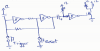
so someone suggested me to modify the circuit above by plugging in this circuit below after the pin 3 which is output to protect the circuit.
**broken link removed**


so i am a little confused as can there be an alternative to the circuit above as it looks too complicated? I know i will need a diode connected in parallel to solenoid to prevent back emf but exactly don't understand why are transistors required? if transistors are required then what type of transistors do I use?

Also does this look achievable?

Waiting for replies!
Thank you
 
Hello again rizla,


Thanks for posting the schematic. I can see it clearly without the web page acting up.

This circuit will require probably only one transistor on the output, with a couple resistors. That should drive your solenoid which you said was 0.5 amp right?

Also, you need an input lockout for the 555 so it only triggers once. You may want to verify the pulse output time is between 0.2 seconds and 1 second.

The input lockout can be as simple as a capacitor that couples the switch to the input, with a pullup resistor, and a protection diode from trigger to the positive supply voltage.

Does this make sense so far?
 

Attachments

  • SOLENO1.gif
    SOLENO1.gif
    4.5 KB · Views: 932
Last edited:
I always thought airbags were inflated by an electrically-fired explosive charge? Oh well, I suppose there are other options :).
Also the valves chosen are 12 V, 0.5 A and can go up to the maximum speed of 200 milisecond.
:confused: Do you mean the solenoid needs to be energised for at least 200mS to operate?
can there be an alternative to the circuit above as it looks too complicated?
Yes. You can omit Q2 and Q3 and their associated components. A 555 can drive a suitable FET directly.
an airbag go will off instantly
It's supposed to!
Also, you need an input lockout for the 555 so it only triggers once.
Why? Airbags are use-once-only things. In an accident there would only be a single trigger. Besides, surely it won't matter if the valve opens repeatedly after the bag has deployed?

Edit:
If this is a hypothetical system, e.g. for a school project, then fine. If it's for a real-life airbag system then a lot more needs to be done to prevent any possibility of false triggering, e.g. by voltage spikes on the 12V supply.
 
Last edited:
I always thought airbags were inflated by an electrically-fired explosive charge? Oh well, I suppose there are other options :).
:confused: Do you mean the solenoid needs to be energised for at least 200mS to operate?
Yes. You can omit Q2 and Q3 and their associated components. A 555 can drive a suitable FET directly.
It's supposed to!
Why? Airbags are use-once-only things. In an accident there would only be a single trigger. Besides, surely it won't matter if the valve opens repeatedly after the bag has deployed?

Edit:
If this is a hypothetical system, e.g. for a school project, then fine. If it's for a real-life airbag system then a lot more needs to be done to prevent any possibility of false triggering, e.g. by voltage spikes on the 12V supply.
yes well opening and closing time is 200 milisecond!

no its not for real life! we have the car engine stripped off and we are using compressed air system to trigger airbags!
so in this simulator we will use airbags made of another material which can be reused again and again! its going to be like this once an airbag has gone off it will be repacked into its casing then you press the button, it will go off again!
 
Hello again rizla,


Thanks for posting the schematic. I can see it clearly without the web page acting up.

This circuit will require probably only one transistor on the output, with a couple resistors. That should drive your solenoid which you said was 0.5 amp right?

Also, you need an input lockout for the 555 so it only triggers once. You may want to verify the pulse output time is between 0.2 seconds and 1 second.

The input lockout can be as simple as a capacitor that couples the switch to the input, with a pullup resistor, and a protection diode from trigger to the positive supply voltage.

Does this make sense so far?

yes the solenoid of 0.5 amp i have to drive! what is the purpose of input lockout system? :S
Thanks for the schematic so if i use this circuit on the output of my 555 ie pin 3 would that be fine?
 
yes well opening and closing time is 200 milisecond!
So it takes 200ms to open the valve. How long does it need to stay open to inflate the airbag?
 
So it takes 200ms to open the valve. How long does it need to stay open to inflate the airbag?

well in our group meeting the only info given to me was that i have to make this circuit which can be used for 0 to 1 second time!
 
Hi,

Yes the more details you can find out the better this would work.

The input lockout, again, is a small simple circuit that locks out the trigger input so that if the switch is held down for too long (longer than the timer period) the output can function properly. If the switch is pushed down and isnt released fast enough, the output pulse follows the switch opening and NOT the required capacitor/resistor time period. So input lockout will mean pressing the switch once and then releasing it later operates the air bag only once.
Another problem this takes care of is if the switch is released later some time the bounce might cause another coil firing.

Another possible requirement is that the reset pin be held low during turn on of the circuit, so that the valve doesnt accidentally fire during turn on of the circuit. We'd have to test the actual device to find out for sure, unless someone here would like to perform a few simple tests with a 555 and scope.
 
If you must have input lockout and must use a 555 then a latch with a 'trigger' button and a separate 'reset' button could be used for the lockout.
 
Hi,

Yes the more details you can find out the better this would work.

The input lockout, again, is a small simple circuit that locks out the trigger input so that if the switch is held down for too long (longer than the timer period) the output can function properly. If the switch is pushed down and isnt released fast enough, the output pulse follows the switch opening and NOT the required capacitor/resistor time period. So input lockout will mean pressing the switch once and then releasing it later operates the air bag only once.
Another problem this takes care of is if the switch is released later some time the bounce might cause another coil firing.

Another possible requirement is that the reset pin be held low during turn on of the circuit, so that the valve doesnt accidentally fire during turn on of the circuit. We'd have to test the actual device to find out for sure, unless someone here would like to perform a few simple tests with a 555 and scope.


Oh thank you! now it does make sense to me the input lockout! so if I use a 47uF capacitor coupled with 1k ohm resistor and a diode say the same as for the solenoid 1N4007 before the push button input ie from from pin 2 will I be then able to achieve the input lockout?
 
Last edited:
Here's one way you could do it. This circuit also keeps the 555 reset at power-up.
Lockout.gif
 
Oh thank you! now it does make sense to me the input lockout! so if I use a 47uF capacitor coupled with 1k ohm resistor and a diode say the same as for the solenoid 1N4007 before the push button input ie from from pin 2 will I be then able to achieve the input lockout?


Hello again,


Show your circuit you have described and we can take a look.

I was assuming that when the 555 fires it energizes the valve coil and that shoots air into the bag for say 200ms. But if they 555 fired again it would shoot more air into the bag possibly damaging it, or is that not a problem?

So as alec says, if you want we can use a separate switch to reset the 555 just before you're ready to fire it.

I'm also asking about this in another thread. What we need to know is how critical a second firing would be. Would it hurt to fire it again later by accident? Maybe the only way is with two switches...one to "arm" the circuit and one to actually "fire" the circuit.

ADDED LATER:
It looks like the circuit posted by alec in post #11 should do it. Since the timer doesnt have to produce a really really short pulse, the capacitor coupling should be ok, and combined with the latch on the input that will lock out future mis-triggers. We should really do something like that for this application so there is absolutely no chance of unwanted triggering.
Remember also that we need to test the circuit for the time when it is first turned on too. The RESET pin might have to be held low during turn on.
We also have to add a diode across R3 to protect the 555 when the capacitor resets (circuit in post #11).

alec:
What's the additional 47k resistor to the 555 trigger input for?
Also, R6 is too large in value.
 
Last edited:
What's the additional 47k resistor to the 555 trigger input for?
Also, R6 is too large in value.
Just guessing, but the 47k (R5) looks like it's there to protect the trigger input from the 24V on C1 when the output of U1a goes high. Again, just guessing, but R6 would appear to be there to protect the 555 and the pot when the pot value is low...
 
If we're talking about the circuit I attached in post #11 then spot on, dougy, re R5 and R6. R6 also protects against excessive discharge current if C6 had a much higher value.
We also have to add a diode across R3 to protect the 555 when the capacitor resets
Optional. R5 should keep the 555 safe.
C2 might need to be increased if the power supply rise time is slow.
A cap (1u?) from R2 to ground might also be advantageous, to ensure the latch starts in the right state at power-up.
 
Last edited:
Hello,


Ok, so the additional 47k is there to protect the 555, but do all 555's have built in protection diodes? I dont think so, probably only the CMOS versions. That's why i suggest an external diode.
 
do all 555's have built in protection diodes? I dont think so, probably only the CMOS versions.
I've just re-checked TI's NE555 (non-CMOS) datasheet and there's no obvious protection diode so yes, an external diode should be added. My bad. Good catch.
 
Here's an alternative, using a 556 (= two x 555) to reduce the IC count. Operation is similar to my previous circuit except that the 2-gate latch is replaced by 1/2 NE556 and a transistor inverts its output to trigger the other 1/2 NE556.
Lockout2.gif
 
Equivalent to the above latching circuit but with fewer parts:
 

Attachments

  • latch_timer.png
    latch_timer.png
    9.8 KB · Views: 539
Hi dougy,


Good idea, but you arent suggesting that he use this to also replace the 555 are you?
I ask because we need a reasonably accurate time delay which isnt that reliable with just a cap, resistor, and regular Schmitt trigger logic chip.
I do like the latch part though.

I guess we are waiting now to see what the OP wants to use more or less. But i think a 555 or similar chip is needed for the accuracy and repeatability of the timing pulse.
 
Yes, I was proposing the replacement of the 555s with the schmitt trigger. Accuracy is not an issue as the time is set using a variable resistor. Repeatability should be OK, though might change slightly with temperature (but so will the R & C values). The threshold voltage temp-co is 0.0005 V/C for 74C914 (https://www.electro-tech-online.com/custompdfs/2013/03/snos344a.pdf)
 
Last edited:
Status
Not open for further replies.

Latest threads

New Articles From Microcontroller Tips

Back
Top