Andy1845c
Active Member
I have been kicking around the idea of getting back on the ham radio air waves. I would like to be able to work 40 meters, but don't have 70 feet of clear space to install a dipole. I am thinking of trying a magnetic loop antenna. Here is a site about what I am looking at. Magnetic Loop Antennas, Magnetic Loop Info, How to Build A Magnetic Loop, W2BRI Loops
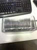
I don't have alot of extra cash to buy a fancy variable capacitor at the moment. I do however have about 200 3" x 3" x 1/16th aluminum plates.
What I lack is knowledge figuring out the number of plates, shape of plates and spacing I will need to make my own capacitor. Something like 40-600pf seems to be what most plans mention. I can only output 100 watts with my radio. The author of the page in my link says he has used 4KV caps at 100W with no arcing. So possibly something arounf 4 or 5KV would work for me. I don't know how to
Can anyone guide me on how I could start out on this? I should also mention I don't have a meter that will measure capacitors. So I imagine It will be alot of trial and error.
Are there any math formulas that I could possibly use.
Any words of wisdom from the resident radio experts?