Electronic Circuits and Projects Forum


L298 Short-circuit protection

1234 Last »
  1. #1
    stevenh stevenh is offline

    L298 Short-circuit protection

    To everyone, from a fairly uneducated newbie

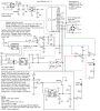
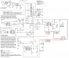
    I've just recently completed a DCC (Model Railway Command Control) Booster Circuit of which I can successfully control my DCC-equipped trains from my com port. A schematic of the circuit is here: [See attachment: 941202_s.gif]

    I've realised one huge issue though... if the tracks happen to short then things start either cooking or exploding; which, as you could imagine, is not the result I'm after...

    I'd read the information on page 3 of this document [See Attachment: 1681.pdf]
    and attempted to apply it between '1EN' and the L298 but to no avail...

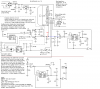
    I then saw a similar circuit here: [See Attachment: bstr-1.gif]
    that ties the 'current sense' pin to ground with a huge 0.47/5Watt resistor but also feeds it back into a TL072 to disable the input (although it doesn't seem to control the actual '1EN' pin?)

    Due to a lack of knowledge though, I have no idea how to combine this into the current schematic as the 'current sense' pin is already tied to the feedback circuit and the '1EN' is tied into the 555 timer to only enable the output on data input...

    I imagine I need a way of combining the 555 input into an AND gate of some form? Or something similar to only enable when the current sense is minimal? 3-4A would be a good current rating... but anything above 1A is great.

    I'm currently using a ~13.8v DC transformer to power the circuit.

    Any help would be greatly appreciated

    (Apologies for attaching everything... I couldn't post links as it's my first post?)

    Thanks, Steven.
    Attached Images
    Attached Files
    Last edited by stevenh; 7th October 2008 at 10:06 AM. Reason: Added apology.

  2. #2
    MrAl MrAl is offline
    Hi there,

    From the sound of it, the first thing you should do is verify that you are able
    to DISABLE the bridge with the enable pin. Make sure when you switch that
    high and low that the output turns on and turns off as it should. Get this
    working first.
    Next, you can build a simple 'pulse catcher' with two sections of LM339 alone.
    The idea is that the first LM339 will catch a current pulse (or level) that is
    too high and trigger the next LM339 section, and that will turn off the enable
    signal to shut off the bridge. The bridge will then stay off for a certain period
    determined by the capacitor and resistor you use on the output of the first
    LM339.
    The .47 ohm resistor (if that is appropriately sized) drops some voltage and
    that is sensed by the first LM339 setup to detect a voltage level I/0.47, and
    the output of that stage is a cap to ground and resistor to V+. When
    the LM339 trips, it discharges the cap, and that is sensed by the next
    stage. Once the current goes back to normal or lower, the cap starts
    to charge up and after some time the bridge is switched back on.
    If the problem still exits, the bridge is shut down again, etc., and this
    repeats until the problem is corrected. Since the delay time can be
    made large (100ms or even longer) the bridge does not heat up.
    Total devices required: one LM339 package and a few resistors and
    one capacitor say 0.1uf or so.
    0

  3. #3
    stevenh stevenh is offline
    Ok,
    So the LM339 sees the reference voltage at the negative input (of each comparator) and as long as the voltage at + is lower it will keep the output pinned to ground (or low...)

    So what I would need to work out is how to make sure that when over-current occurs the sense pin will raise the voltage to above a certain level... Should I slap a multimeter on there and short the circuit out briefly to measure what comes through?

    I've made up a design to incorporate these two comparators and it sorta makes sense to me but the resistors required are beyond me.

    I would imagine the initial feed from the 555 circuit needs to be lowered from +5v since that's the comparative voltage and I don't know if the voltage out of the current sense pin will exceed that?

    Also, the 0.1uf cap will provide the timing... 100ms = 0.1uf? I'd nearly like the timeout to be 1000ms since times to find faults would exceed this easily and I'm happy for power to be cut off for longer periods.

    Another nice advantage would be an LED when the voltage is cut... is there a chance to use an inverter between the two comparators (as the 7404 has been doing, although it's all used up) to slap an LED in (as seen in the 555 circuit) to show the overload status?

    Thanks again for your help.
    Attached Images
    0
    Last edited by stevenh; 8th October 2008 at 01:13 AM.

  4. #4
    MrAl MrAl is offline
    Hi again,


    Do you know how to calculate resistor dividers to get a lower reference
    voltage from a higher voltage like 5v?

    The idea is to make the first comparator section sense the voltage across
    the 0.47 ohm resistor so you need one divider set to that voltage, and
    that gets compared to the sense voltage (voltage across 0.47 ohms resistor).
    That discharges a cap and the next comparator senses that and disables
    the L298. No 555's required.

    The charge time of a resistor and capacitor is equal to the time constant
    (sometimes simply called TC) and that is the time it takes the cap to charge
    to 63 percent of the supply voltage. If the supply voltage is 5v, then
    63 percent of that is 3.15v, so we would make one divider that produces
    a voltage of 3.15v and apply that to one comparator input. One time
    constant is easy to calculate too so we can figure the cap value and its
    resistor: 1 TC=C*R, with C in farads and R in ohms. It takes t seconds
    for the cap to charge to 3.15v then t=1TC=C*R. With a 1uf cap and
    100k resistor this works out to 0.1 seconds (100ms). If you want 1 second
    then a good idea would be to go with a 10uf cap and 100k, or 5uf and 200k.
    Since the cap is a bit large it would also be a good idea to beef up the
    output of the LM339 with a single NPN transistor. This will speed up the
    response to an overcurrent.

    To test the circuit for overcurrent to see what voltage you get across
    your resistor, it would be a good idea to know what the current is
    normally. In other words, what is the current when everything is
    working normally? You would want to measure the voltage across the
    sense resistor when the current is just above this level or when
    whatever you are powering (motor, etc.) is running normally. You
    dont want it to trip when it is running normally, but you do when
    something goes wrong. Depending on the current you may also have
    to switch the 0.47 ohm to something else, like 0.1 or whatever.
    An adjustment would be nice too, so the current trip point could
    be adjusted during some tests.


    Yes adding an LED wont be hard to do.


    Perhaps i should make a schematic and post it here for you to take a look
    at? I need to know what the normal current draw is for whatever you are
    powering first.
    0
    Last edited by MrAl; 8th October 2008 at 07:16 AM.

  5. #5
    stevenh stevenh is offline
    Quote Originally Posted by MrAl View Post
    Do you know how to calculate resistor dividers to get a lower reference voltage from a higher voltage like 5v?
    I have never really done this form of electronics math but do want to learn... am a software engineer by trade and haven't delved into hardware too much.

    Quote Originally Posted by MrAl View Post
    No 555's required.
    The 555 I refer to is th e cut-off circuit that already exists on the lower half of the diagram to force the enable pin high if there is no incoming data.

    The enable pin (when pulled low) does disable the output. I tested this by disconnecting the input to it and grounding it intermittently.

    Quote Originally Posted by MrAl View Post
    I need to know what the normal current draw is for whatever you are powering first.
    Currently the system takes around 500mA per train on the track (but this varies depending on brand/headlights/etc...)

    I'd be happy to limit the booster at 4Amp.

    My multimeter currently can only show up to 200mA and when two locos are sitting still it's at 154mA and as soon as I set a throttle or headlight on either the multimeter just shows "1" since it can't go any higher.

    I'm about to slap the multimeter on the 'current sense' pin and see what happens when I short the tracks.

    Voltage on Pin 1 rises to 0.91v when the tracks are shorted
    ...this would mean that I need to lower the input voltage into the first LM339 + to anything between 0.1 and 0.5 (as the voltage on pin 1 climbs gradually, although quickly, to 0.91) ??


    Thanks heaps for your help on this.
    0
    Last edited by stevenh; 8th October 2008 at 09:32 AM. Reason: Added findings from shorting tracks.

  6. #6
    MrAl MrAl is offline
    Hi again,


    The output voltage of a resistive divider is calculated as:

    Vout=Vin*RLow/(RHigh+RLow)
    where
    Vin is the voltage applied to the top of the divider
    RHigh is the upper resistor
    RLow is the lower resistor

    This helps to calculate trip points for comparator circuits like we are
    talking about here.

    If you have several circuits that need to disable the L298 for some
    reason then you need to logical AND all the outputs together and
    feed the L298 with the output of the AND gate. What this does
    basically is says that every output must be high in order to
    enable the L298. If any single one goes low, it shuts the output off.

    This current trip circuit i am posting works by detecting the current
    and shuts the output off for 1.1 seconds. It's ok if it cycles like
    that if there is a short or something.
    You do need to make sure your 5v supply remains at 5v during a short
    too however.

    Here's a typical schematic. Since you are already using 555's this includes one.

    0

  7. #7
    stevenh stevenh is offline
    Ok, based on the original circuit above.. I have added in your trip circuit. It seems that if i remove the 'feedback' portion to the left of the sense pin 1 and just take that pin straight into your circuit then I can't get the L298 to enable.. even though there is ~3.9v outputted to pin 6 (enable).

    But... leaving that feedback side connected and then joining on your trip circuit (with both the 0.47R to ground in the feedback circuit and then another two 0.47R in series as I don't have 0.5R and one 0.47R would cause it to trip too early on your trip circuit) made everything work...

    I don't totally understand the implications of now having pin 1 brought to ground with the original 0.47R + 2x0.47R in this additional circuit... but I imagine it raises the 'allowed' amps through.

    I'm going to leave this for tonight and might make more sense of it tomorrow... but so far so good, even if I am just applying guesswork
    0

  8. #8
    MrAl MrAl is offline
    Hi again,

    I think you should redraw the schematic you are using now, as the old one
    isnt the same now. Also, in that old schematic i see that two of the
    comparators (at least) are not connected correctly for the operation you
    want.
    0

  9. #9
    stevenh stevenh is offline
    Here's the latest.... cutting the circuit at the line marked 'cut' will stop the enable pin from working... i.e. the whole trip circuit just stays tripped for some unknown reason... it could also be that i'm not bringing the enable pin high enough due to my use of incorrectly valued resistors... since it turns out that my 0.47 resistors are actually 0.27R/5W... I tried adding in another 0.27 in parallel to the 2x0.27 (i.e. 0.52 in parallel with 0.27) as that's what i'm cutting off when i remove the feedback circuit but that didn't help either.

    I need to source some 0.47 resistors from somewhere

    On the up-side... everything still works great when both the feedback circuit and trip circuit are connected... I get the ~1.1s timeout and then it all comes back to life... no arching (well, buzzing) from the shorted item when across the tracks anymore.
    Attached Images
    0
    Last edited by stevenh; 8th October 2008 at 10:30 PM.

  10. #10
    MrAl MrAl is offline
    Hi again,


    You see that LM339 pin 2 that is connected to the 555?
    That section needs to have pin 5 and 4 swapped.
    That is, connect the sense resistor to pin 4 and the
    resistor divider to pin 5. Test with that circuit alone
    as you did before, that's a good idea.
    You should see your train or whatever run normally until
    there is an overcurrent, and then it will appear to shut
    off. If it shuts off when the train starts to move,
    that means the current sense is too sensitive. You
    might try paralleling some 0.47 ohm resistors (or whatever
    you have on hand) to beef up the current trip point.
    This also keeps power dissipation in the sense resistor
    low too, but if that's not a problem (sense resistor does
    not heat up) you can also adjust the resistor divider a bit.
    Before you do that however try to get this working with
    one train alone.

    BTW, with that 10uf cap instead of 1uf you might get
    more like 10 seconds between current 'tries', if that's
    ok then dont worry about it. Note also that you may
    not see this happen, because the LM339 is pretty fast,
    so it would turn off fast, then turn on for possibly only
    10us, then turn off again. You might not see this happen
    but it will be working. Once the short is removed,
    up to 10 seconds later the train will start moving again.
    It may take the full 10 seconds to start again due to the
    10uf cap as noted above.

    If you want an LED to show when the current is being
    cutback (turned off) you can connect an LED to a
    2.2k resistor to +5v (anode toward +5v) and connect
    that resistor to the output of another inverter, then
    connect the input of that new inverter to the output
    of the 555. When the current shuts off, the LED will
    light. Note however that when there is a short it
    may appear to stay lit and not go out, even after 10
    seconds, because the pulse will be very short. After
    the short is removed the LED should go out after
    a max of about 10 seconds and the train should start
    to move again.

    There is also the possibility that when the train starts up
    the surge current trips the current sense. We'll have
    to deal with that too if that happens.

    What power rating are your sense resistors?
    0
    Last edited by MrAl; 9th October 2008 at 09:26 AM.

1234 Last »
Tags
Similar Threads
Thread Starter Forum Replies Last Post
Hot Short Protection circuit doverbuzz Electronic Projects Design/Ideas/Reviews 16 7th February 2010, 01:46 AM
short circuit protection raed Electronic Projects Design/Ideas/Reviews 2 16th March 2008, 08:31 PM
L298/L297 Circuit baberjaved Robotics & Mechatronics 0 23rd September 2007, 08:11 PM
Short circuit protection problems Exo Electronic Projects Design/Ideas/Reviews 2 10th April 2005, 01:57 PM
Short circuit protection curious General Electronics Chat 5 11th February 2005, 06:39 PM
Electronic Circuits  |  Learning Electronics

Join our community with over 100,000 Members! It's free, easy and when you're logged in you have many more features! Click to register.
Page Time: 0.05286 seconds      Memory: 7,396 KB      Queries: 17      Templates: 0