Electronic Projects, forums and more.

Go Back   Electronic Circuits Projects Diagrams Free > Electronics Forums > General Electronics Chat


General Electronics Chat This forum is for general chat about electronics, eg: Dont know what a part does? Dont know how to read a circuit? Want to get an opinion?

Reply
 
LinkBack (1) Thread Tools Display Modes
Old 15th June 2006, 09:04 PM   1 links from elsewhere to this Post. Click to view. (permalink)
Thumbs up Now that's a project..

Plodding through the net I came across an thought provoking little snippit..
-----------------------------------
In 1977, Forrest M. Mims reminds us in one of his "Engineer's Notebooks" that LEDs can also be used as photodiodes...
-----------------------------------
Then I found this and my jaw dropped, open mouthed scratching the stubble on my chin... OOOOOOOOOhhhhhh yes I said to myself, I like that.

http://mrl.nyu.edu/~jhan/ledtouch/index.html
12MB of video to download
Attached Files
File Type: pdf leds as input device.pdf (530.9 KB, 250 views)
__________________
It may seem like a good idea at the time , but never stir your cold coffee with a soldering iron.

Last edited by The Mad Professor; 15th June 2006 at 10:06 PM.
The Mad Professor is offline  
Old 15th June 2006, 10:01 PM   (permalink)
Default

That is a really cool demo.

I'm guessing he's using the reflected light as a proximity sensor. It's just like all the LED/phototrasistor paired proximity sensors, only using the LED as both the light source and the detector. It's interesting, but it's obviously limited just like a regular Prox sensor. Ambient light and changes in ambient light have to be adjusted for. Shadows, anything like that can cause unwanted readings, or make it unusable.

I like how he's using actual proximity reading and not just on/off sensing.
__________________
Mark Higgins
DirtyLude is offline  
Old 15th June 2006, 10:36 PM   (permalink)
Default

there's a couple threads from some guy who spent months experimenting with this. he says its' capacitive. he wound up concluding that it's not very cost effective. I'm just telling ya what he said .
philba is offline  
Old 16th June 2006, 03:00 PM   (permalink)
Default

Well, it looks like the Mad Prof added a PDF file which I assume is related to the video. The PDF describes using the LED's as photo emmiters and detectors, so in this case, I'm assuming it's not ussing capacitive sensing.
__________________
Mark Higgins
DirtyLude is offline  
Old 16th June 2006, 03:52 PM   (permalink)
Default

It's funny this topic comes up, I recently obtained a collection of most of Mims' Engineer's Mini-Notebooks, and although now 20-30 years old they hold up well and are full of great ideas and circuit designs. I don't have the one that details the detection experiment, but he does make references to led light sensitivity.

I got interested and did some Googling, here are some relavent links I have found...

justDIY - LED's as sensors
Sensor Synergy
Led's as light sensors
agent420 is offline  
Old 16th June 2006, 08:22 PM   (permalink)
Default

Ambient light according to the text is less of a problem than anybody thought as the peak wavelength responce of the of the LED in "detector" mode is closely related to its emission characteristics. Sadly the the responce times may be a bit slow for high speed data exchange , but it certainly looks like a keypad or dare I say keyboard ,could be done.

I would be interested to hear what our resident PIC programers have to say,
and wonder how the process holds up when a Bi-Colour LED is used?
__________________
It may seem like a good idea at the time , but never stir your cold coffee with a soldering iron.
The Mad Professor is offline  
Old 2nd July 2006, 01:38 PM   (permalink)
Question Want to know more?

Go here: http://www.electro-tech-online.com/s...202#post146202 and try to answer the questions...
mcs51mc is offline  
Old 3rd July 2006, 06:38 PM   (permalink)
Default

I've had this idea before but I've had no application for it, however I wasn't clever enough to think about the reverse bias capacitance of the LED.
__________________
I also post at the following sites:
http://www.stop-microsoft.org http://www.heated-debates.com
Screen name: Aloone_Jonez
And http://www.silicontronics.com, same screen name as here.
Hero999 is offline  
Old 7th July 2006, 11:22 PM   (permalink)
Default

I was thinking that another application of using a LED as a light sensor may be to generate 'random' data to reseed a random number generater using the tapped shift register method. You could have it check the light level every so often, and continously reseed the shift registers on the fly. This should eliminate generating the same pattern of random bits (unless the light level is always exactly the same). Cheap randomizer...

Rick
rockin_rick is offline  
Old 8th July 2006, 12:42 PM   (permalink)
Default

Great idea on the randomizer.

I have cut the tops off a power transistor and seen 1.5 volts+ at very low current. Something else to try in place of the LED?
mramos1 is offline  
Old 30th July 2006, 07:10 PM   (permalink)
Question

I've been trying to make a project like this on a smaller scale but can't get it to work
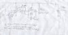
. The LED just stays at the same brightness no matter what the light levels are! It is a clear red 5mm LED. Found the circuit diagram here: http://www.edn.com/contents/images/6335303.pdf (page 5). I haven't got all the components (i.e. MC14528 & OP-90), so have modified the circuit to suit what I have available.
Would you tell me if my circuit looks wrong, please?
Attached Images
File Type: jpg 2_way_led_modified_circuit.jpg (299.7 KB, 73 views)
fingers is offline  
Old 30th July 2006, 07:39 PM   (permalink)
Default

Your power supply voltage is awful darn low. The LM358's output probably doesn't go high enough for the NOT gate, and the output current of the Cmos 555 will be very low.

Your circuit doesn't have a reset when power is applied.
Your circuit also keeps the 555 timing because pin 2 stays low if the NOT gate gets enough input voltage. Capacitor-couple the NOT gate to pin 2 and use a pullup resistor at pin 2 then the circuit might work.
__________________
Uncle $crooge
audioguru is offline  
Old 30th July 2006, 10:54 PM   (permalink)
Default

Damn nice redesign of the original circuit guy. Have you tried the changes that audioguru suggested ?
If it does work, please send me the schematics, or post them here, as * am quite interested.
__________________
SHYTE!
bigkim100 is offline  
Old 30th July 2006, 11:54 PM   (permalink)
Default

You can eliminate the "not gate" (inverter) if you swap pins 5&6 on the LM358. Like AudioGuru stated, you need to capacitively couple pin 2 of the 555 which will then need a pullup resistor also. This is because the output of pin3 on the 555 will NOT return to the inactive state as long as pin 2 is low. Also, you'll need a diode in series with R5 because when pin3 of the 555 is low it will drain any voltage (through R5) that the LED produces when sensing light. A higher supply voltage should be tried if all else fails. Try 5V.

Last edited by kchriste; 30th July 2006 at 11:59 PM.
kchriste is offline  
Old 31st July 2006, 12:19 AM   (permalink)
Default

Quote:
Originally Posted by kchriste
You can eliminate the "not gate" (inverter) if you swap pins 5&6 on the LM358.
Then the high output voltage of the LM358 is about 2.55V-1.2V= 1.25V which is too low for the Cmos 555 which needs at least 2.55V/3 x 2= 1.7V.

Quote:
Also, you'll need a diode in series with R5 because when pin3 of the 555 is low it will drain any voltage (through R5) that the LED produces when sensing light.
Then the voltage for the LED will be even lower than it is without the diode.
I was wondering why the original circuit used the transistor instead of the Q output of the monostable. So that it doesn't load the LED when it shouldn't.
__________________
Uncle $crooge
audioguru is offline  
Reply

Bookmarks

Thread Tools
Display Modes


LinkBacks (?)
LinkBack to this Thread: http://www.electro-tech-online.com/general-electronics-chat/22064-now-s-project.html
Posted By For Type Date
Bot Thoughts: Tinkering Update This thread Refback 26th May 2008 02:02 AM


All times are GMT. The time now is 11:44 AM.


Electronic Circuits  |  Learning Electronics
Powered by vBulletin® Version 3.7.0
Copyright ©2000 - 2009, Jelsoft Enterprises Ltd.

eXTReMe Tracker