Electro Tech is an online community (with over 170,000 members) who enjoy talking about and building electronic circuits, projects and gadgets. To participate you need to register. Registration is free. Click here to register now.
Welcome to our site! Electro Tech is an online community (with over 170,000 members) who enjoy talking about and building electronic circuits, projects and gadgets. To participate you need to register. Registration is free. Click here to register now.
Does anybody have a site that explains (preferably with diagrams/pictures) how to wind a transformer? Possibly with more that one type of core (E-E prefered).
I dont need to know how to design a transformer, just want a tutorial on proper winding techniques.
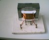
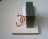
here is one of my home made transformers, i took the core from an old knakked one. It has a turn ratio of some thing like 200:1, i used it to step 12V up to about 2,400V. the plastic you can see started life as square PVC drainpipe, i shaped it with the heat from a soldering iron. the wire guage on the outside is #18SWG and internal is #32SWG. i wound it with a drill, another method is to wind the primary on the bottom half of the core and the secondary on the top. this transformer does not work as i killed it with overvoltage, was pretty funny though.
below are some links http://www.geofex.com/Article_Folders/xformer_des/xformer.htm http://www.obsoleteelectronics.com/Transformers/About_Transformers/about_transformers.htm
Also, is there a website similar to digikey that sells ferrite cores, bobbin, wires, and other custom transformer accessories? I want to order some magnetics inc materials but it looks like their only distrubors only sell for large scale distrubition. All I want to do is order about 5-10 cores, bobbins, and wires.
A $50 minimum is fine. I just didnt want to order from a distubuter wanting minimum orders of $1000 or something aimed at mass selling to businesses.
I'm trying to make a high frequency transformer for a SMPS. I still need to learn a bit about how to wind a transformer, so I will probably be ordering a few E and I cores to play with along with some wire, laminates, tape, and bobbin.
Any info on where I can aquire some of these would be appretiated.
Before you try to buy any cores you better read up on Magnetics and Ferrite transformers.
Dexter Magnetics is a Good Supplier of various ferrites from various manufacturers. (Fair-Rite, Philips, Magnetics, and many more) They just sell the Ferrites and Bobbins. NO Wire.
1-800-775-3829
If your trying to build a high power, high frequency unit, I would recommend a Fair-Rite E-core, using Material 77.
You Need to also Understand "AL" Values and how to Properly Gap the Ferrites.
There is an article on "AL Value Calculations" on my Website.
Additionally, if you plan to have a DC Output, Remember that High Frequency Requires Special Diodes.
Also, Depending on What you want? I can possibly also supply some Ferrites, as well as wire. But you need to email me direct, with some more Specific info of What you are trying to make. (Current Requirement, Voltages involved, Frequency, etc.)
here is one of my home made transformers, i took the core from an old knakked one. It has a turn ratio of some thing like 200:1, i used it to step 12V up to about 2,400V. the plastic you can see started life as square PVC drainpipe, i shaped it with the heat from a soldering iron. the wire guage on the outside is #18SWG and internal is #32SWG. i wound it with a drill, another method is to wind the primary on the bottom half of the core and the secondary on the top. this transformer does not work as i killed it with overvoltage, was pretty funny though.
below are some links http://www.geofex.com/Article_Folders/xformer_des/xformer.htm http://www.obsoleteelectronics.com/Transformers/About_Transformers/about_transformers.htm
**broken link removed** **broken link removed** **broken link removed** **broken link removed**
those pics are not the best as they were taken with my old cam...a Kodak MC3
2 with about 50 turns of 12 gauge wire...solid, and the other side is left untouched with what looks to be 14 or 16 wire
just used chiseled off one side of the secondary and after it looked like a "C" from the top view I used a wood punch to hammer the wire out of the slots
I was always told it was better to keep a trans. closed up...even when working on it as after opening high current ones, its hard to keep them from buzzing and heating up allot.....on top of that its just hard grinding out a weld then putting the trans back together
BTW those transformers in the stick welder put out about 80V and 90A
On a related note, Nuts & Volts magazine published plans for a coil winder project recently you might be interested in tracking down.
Looks like a zip file of the plans can be found here: **broken link removed**
1. Do you know about the transformer use in the common mobile phone charger? It is a step down transformer right?So here i want to ask, can i modified the transformer so that it can be a STEP UP TRANSFORMER?
2. Lets say the step down transformer in the mobile phone charger step down 240V to 5V, can it be reversed back so that it can step up from 5V to 240V back? Will it possible?
Assuming it's a conventional transformer (and not a switch-mode power supply - but most are), then you can input 5V AC to the secondary, and get 240V AC out of the primary.
But even assuming it's a conventional transformer, you would have to remove it from the chager, as the charger will have a rectifer inside, which will stop it working.
But notice you require an AC power source, not a DC one.
One word of warning, don't expect to be able to connect 5VAC to the secondary of a 240V to 5VAC transformer and get 240VAC. In practice you'll get something closer to 210V which will drop down to 180V with a load connected. Transfromers aren't perfect and there will be losses, especially if it's a small transformer.
My advice is to measure the off load voltage, then connect it up to a voltage source of the same value and the loaded secondary voltage should be pretty close to the mains voltage it's designed to run off.
I've rewound a mains transformer before. I got it from a training centre I used to go to. It was an RS 100VA tranformer kit that had already been assembled and wound to give 19V unloaded. This was no good for me so I decided to turn it into an isolation transformer. I worked out the number of volts per turn by unwinding it can counting the number of turns and dividing the measured voltage by the number of turns.
When I rewound it I increased the number of turns by about 15% in the knowledge that the voltage will drop when a load is connected. After winding 1200 or so turns I connected the mains to the primary and measured the secondary voltage. With 230V on the primary, the secondary measured about 250V, I connected a 100W light bulb to the secondary and the voltage dropped to just below the input voltage. I tried connecting the secondary to the mains and the primary voltage was about 210V - I didn't bother connecting any loads as this isn't of any use to me.
I'm set to wind a transformer for the very first time and would welcome any pointers, gotcha's, etc.
ETD34 core
primary: 12T, center tap, #18AWG
secondary: 275T, #24AWG
I have a few "elementary" questions:
Is there an easy way to count the 275 turns? ...does anyone have a makeshift apparatus to help with this?
How to do the center tap? I've read two ways to do it: 1) double over the wire and wind and then join one starting end with the other finishing end 2) "dimple" the wire half way and solder in the center tap
Which gets wound first? ...the long secondary or the short primary?
How important is neatness? ...can the coils of one row "cross over" each other?
I use a meccano winder with an old counter from a gas meter to count the turns.
Neatness is important to keep minimum voltage difference between turns. a layer of insulating material between layers of windings is good practise although it makes the transformer coil bigger.
Usually the secondary is closesd to the iron yoke.
That depends on the voltage per layer. Mains transformers generally don't need any insulation. I's only when you start getting intohigh voltages (over about 1kV) that you have to worry about insulation.
Wow! This is a great! A place where someone knows about transformers.
I need a little help. Here are the details and what I am attempting to do.....
My power supply is a 12 vdc car battery. I would like to step up the voltage AND current. I know that trade off. The end result should be 100 plus volts and high amps.
The best results we have had so far was to build a audio amp from the plans we found on the internet and the transformer was 14 gauge for the primary with 24 turns and then we used 4 stands of 20 gauge wound at 96 turns.
We need the final out put to be DC and high voltage and high current. Any ideas what to build or what to do here? What I dont understand are the car audio systems. The show power amp with 1200 W. That means 100 amps? How does the car battery sustain that out put? Or am I misunderstanding something.
So if anyone has any ideas how I can get to the end result?
NOt Sure What Amplifier your Talking about, But that 1200 watts is probably PEAK MUSIC POWER. NOT True "RMS" WATTS.
Its unlikely any Car battery/alternator could ever deliver that power on a continuous basis.
WHAT is the Purpose for the High Voltage/Current that your trying to obtain?
And 100 Plus Volts at WHAT HIGH AMPS?
Be Aware, Output power EQUILS Input Power, Plus Circuit Efficiency.
And to convert it Back to DC, results in MORE Inefficiencies.
can anybody tell me i have a three phase 440v supply at my place. i use a single phase stablian zer. but due to voltage drop it does not work good. now i want to make a stablizer that can convert 2 or 3 phase to perfect 230v ac supply can any body tell me about data fortransformer winding.i have a voltage drop problem.some time all phase may show less then 150v too
This site uses cookies to help personalise content, tailor your experience and to keep you logged in if you register.
By continuing to use this site, you are consenting to our use of cookies.

")