Mike - K8LH
Well-Known Member
Hi Guys,
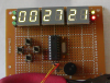
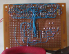
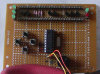
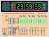
After designing this single chip Charlieplexed 24 hour Clock/Calendar/Timer well over a year ago, I finally found some time to prototype it and it seems to work pretty well.
The Charlieplexed display uses direct I/O drive on the segment lines and this limits 'peak' and 'average' current and display brightness. I'm using relatively efficient displays but the display is by no means "full brightness".
Software was written using the free/Lite version of Sourceboost BoostC.
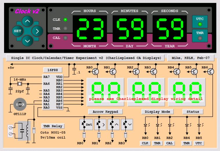
I'm using a four push button "diamond" configuration to control everything. The buttons are fully debounced (both press and release cycles) and there's a short switch press beep through the piezo speaker for positive feedback. The Left button is used to toggle between "display" mode and "set" mode. The <up arrow>, <down arrow>, and <right arrow> buttons perform different tasks depending on whether you're in "display" mode or "set" mode.
In "display" mode, pressing the <up arrow> or <down arrow> buttons cycles the display between the 'Clock', 'Timer', 'Calendar, or 'Display Off'. Use the <right arrow> button to toggle a function associated with the current display on or off. For example, pushing the <right arrow> button while displaying the 'Clock' will toggle the display between local time and UTC. Pushing the <right arrow> while displaying the 'Timer' will toggle the Timer on and off (the red timer LED indicates Timer on/off status). Currently there is no <right arrow> function for the Calendar display.
Press the "set" button to enter "set" mode to edit the current display data (Clock, Timer, or Calendar). The left most display group (Hours/Months) will flash at a 2 Hz rate. Use the <up arrow> and <down arrow> buttons to increment or decrement the display group. The group values will roll over from upper limit to lower limit, or vice versa. Use the <right arrow> button to move to the next display group to the right. When you're at the right most display group, pressing <right arrow> again will move you back to the left most hours/months display group. When finished editing press the "set" button to copy the edited data back to the source (Clock, Timer, or Calendar).
Check for source code updates here; **broken link removed**
The displays are non-multiplexed common anode type. The NPN transistors are 2N3904. The NPN base resistors are missing on this prototype but should be between 500 and 1000 ohms.
Regards, Mike
After designing this single chip Charlieplexed 24 hour Clock/Calendar/Timer well over a year ago, I finally found some time to prototype it and it seems to work pretty well.
The Charlieplexed display uses direct I/O drive on the segment lines and this limits 'peak' and 'average' current and display brightness. I'm using relatively efficient displays but the display is by no means "full brightness".
Software was written using the free/Lite version of Sourceboost BoostC.
I'm using a four push button "diamond" configuration to control everything. The buttons are fully debounced (both press and release cycles) and there's a short switch press beep through the piezo speaker for positive feedback. The Left button is used to toggle between "display" mode and "set" mode. The <up arrow>, <down arrow>, and <right arrow> buttons perform different tasks depending on whether you're in "display" mode or "set" mode.
In "display" mode, pressing the <up arrow> or <down arrow> buttons cycles the display between the 'Clock', 'Timer', 'Calendar, or 'Display Off'. Use the <right arrow> button to toggle a function associated with the current display on or off. For example, pushing the <right arrow> button while displaying the 'Clock' will toggle the display between local time and UTC. Pushing the <right arrow> while displaying the 'Timer' will toggle the Timer on and off (the red timer LED indicates Timer on/off status). Currently there is no <right arrow> function for the Calendar display.
Press the "set" button to enter "set" mode to edit the current display data (Clock, Timer, or Calendar). The left most display group (Hours/Months) will flash at a 2 Hz rate. Use the <up arrow> and <down arrow> buttons to increment or decrement the display group. The group values will roll over from upper limit to lower limit, or vice versa. Use the <right arrow> button to move to the next display group to the right. When you're at the right most display group, pressing <right arrow> again will move you back to the left most hours/months display group. When finished editing press the "set" button to copy the edited data back to the source (Clock, Timer, or Calendar).
Check for source code updates here; **broken link removed**
The displays are non-multiplexed common anode type. The NPN transistors are 2N3904. The NPN base resistors are missing on this prototype but should be between 500 and 1000 ohms.
Regards, Mike
Attachments
Last edited:

")
 But it looked like a good context for asking the question.
