Electronic Projects, forums and more.

Go Back   Electronic Circuits Projects Diagrams Free > Electronics Forums > Electronic Projects Design/Ideas/Reviews


Electronic Projects Design/Ideas/Reviews Are you building an electronic project or want to? Maybe you need some assistance? Come and submit your electronic questions here and let our experienced members find a solution.

Reply
 
LinkBack Thread Tools Display Modes
Old 23rd September 2003, 06:14 AM   (permalink)
Default Coin Toss: Easy Question

OK, I’m working on a “Coin Toss” project. And I have two schematics:

The pictures are at the bottom.

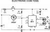
# 1 Uses more parts so not only will it be more complicated, but it will cost more too. The only good thing, is that it runs off of 5V and # 2 runs off of 9V. However, that’s even worse in my case, because they don’t have 5V batteries, as we all know. So, I’ll have to use a voltage regulator, which is big, and needs too be heat sinked. (And of course, will be even MORE money.)

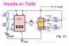
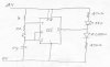
# 2 I would much rather use this one, because… well, I won’t go into a big explanation, so let’s just say it’s because the reasons above do not apply. But the ONLY problem with #2, is that I don’t know what transistor to use. I know it has it right there under the transistor it the schematics, but I can’t really find that one. I use Digi-Key, and their catalog doesn’t show part numbers. So can someone tell me a good transistor to use and give me the Digi-Key part number please? Thank you in advance because I know you guys will be able to figure it out. :wink:
Attached Images
File Type: jpg Coin_Toss_1.JPG (16.0 KB, 1271 views)
File Type: jpg Coin_Toss_2.JPG (23.7 KB, 1262 views)
__________________
When life gives you lemons... make a battery.
Electric Rain is offline  
Old 23rd September 2003, 08:24 AM   (permalink)
Default

Here's some tips:

The transistor: Any UJT (unijunction transistor) will do. 2N2646 and 2N2647 are the most common.

The first schematic: You CAN run it off 9V, and you don't need the 7473. Here is a revised schematic.
Attached Images
File Type: jpg cointoss_161.jpg (22.0 KB, 1244 views)
Phasor is offline  
Old 23rd September 2003, 02:10 PM   (permalink)
Default Are you sure?

Phasor
Are you sure your revised circuit will work as intended?
won't it always stop with the red LED lit?
__________________
I need a memory upgrade ...
My head is full !
mechie is offline  
Old 23rd September 2003, 04:25 PM   (permalink)
Default

Relay strange it realy works!? :shock:

I simulated the circut in Crocodile Tehnology and it worked!???
Someone Electro is offline  
Old 23rd September 2003, 05:52 PM   (permalink)
Default

Yes, it will work. I don't see any problem with Phasor's circuit except for that 1k resistor. It should be atleast of 5k. While designing, that resistor is always taken greater than 5k and accordingly all other component values are calculated.

In practice, capacitor is assumed first and R1 and R2 are calculated on basis of that. But if R1 comes out to be less than 5k, capacitor value is altered to match the requirements.
__________________
"There is no way to peace, peace is the way!"
kinjalgp is offline  
Old 23rd September 2003, 06:45 PM   (permalink)
Default

Yep , Phasor's circuit works fine, i just tried it out on my prototyping board.

But i made some slight changes ;Perhaps its just the type of LEDs im using, but I noticed that when one LED is on the other LED ,which was suppose to be off, glows dimly. So i replaced the 470 ohm resistors with 1K resistors.

I also replaced the .1 uF capacitor with a 4.7uF, so that you can see the LEDs flashing at a high rate when the pushbutton is held down. This makes it abit more interesting.
__________________
Two roads diverged into a woods...i took the one less travelled by. R. Frost.
nettron1000 is offline  
Old 23rd September 2003, 08:03 PM   (permalink)
Default

If you use the "no-latch" circuit, won't the duty cycle asymmetry cause more "greens" than "reds" after many flips? With a CMOS 555, this can be remedied by not using pin 7 or the 1k resistor, instead returning the top end of the 10k to pin 3. The bipolar 555 "high" level on pin 3 does not reach the supply voltage, so asymmetry would still exist.

With either CMOS or bipolar, I suspect that leakage will eventually cause the output to flip on its own. This won't happen with a latch (7473 or 4017).
Roff is offline  
Old 23rd September 2003, 09:49 PM   (permalink)
Default

Quote:
If you use the "no-latch" circuit, won't the duty cycle asymmetry cause more "greens" than "reds" after many flips?
That's why I chose the 1k much smaller than the 10k, to make the duty cycer close to 50%. But statistically speaking, yes, there will be more greens.

Quote:
I suspect that leakage will eventually cause the output to flip on its own
This is true also. Perhaps a low-leakage cap should be used.
Phasor is offline  
Old 23rd September 2003, 10:22 PM   (permalink)
Default

Ive revised the circuit again to account for the duty cycle problem. This one will give a nearly perfect 50/50 duty cyle if you match the timimg resistors as close as possible.

I used 10 K resistors for Ra and Rb( metal film type ) and 4.7Uf for C1, D1 and D2 are 1n914 diodes, power supply was 9 volts.

__________________
Two roads diverged into a woods...i took the one less travelled by. R. Frost.
nettron1000 is offline  
Old 26th March 2004, 02:36 AM   (permalink)
Default

hi all, i got a little problem.I am new to electronics, and i need a lil help.
How do i tell which are base coletor and emmitter in a 2n2646 ujt?
plz, plz! help me, im desperate.
Ian.
(write to ianek@sympatico.ca, or azakovorotny@sympatico.ca)
thnx people.
new is offline  
Old 26th March 2004, 03:24 AM   (permalink)
Default

Quote:
Originally Posted by new
hi all, i got a little problem.I am new to electronics, and i need a lil help.
How do i tell which are base coletor and emmitter in a 2n2646 ujt?
plz, plz! help me, im desperate.
Ian.
(write to ianek@sympatico.ca, or azakovorotny@sympatico.ca)
thnx people.
2N2646 is a UJT. It does not have collector.
Attached Images
File Type: gif 2646.gif (1.6 KB, 899 views)
__________________
"There is no way to peace, peace is the way!"
kinjalgp is offline  
Old 5th July 2007, 04:14 PM   (permalink)
Default

Quote:
Originally Posted by nettron1000
Ive revised the circuit again to account for the duty cycle problem. This one will give a nearly perfect 50/50 duty cyle if you match the timimg resistors as close as possible.

I used 10 K resistors for Ra and Rb( metal film type ) and 4.7Uf for C1, D1 and D2 are 1n914 diodes, power supply was 9 volts.

I thought that the equation for duty cycle was (Ra+Rb)/(Ra+2Rb) therefore, by making the resistors equal the duty cycle becomes 66.7%, the original design would have given a duty cycle of 52.4%, surely much better
professoryak is offline  
Old 5th July 2007, 08:54 PM   (permalink)
Default

This is an old thread but your post is usefull so it doesn't matter.

You really need 50% duty cycle which could be done with a CMOS CD4060 timer oscillator and counter IC.

If you want a cheap circuit then try this circuit, if you use close tollerance capacitors and resistors then the duty cycle should be near enough 50% not to matter.
Attached Images
File Type: gif Decision maker.GIF (10.0 KB, 18 views)
__________________
I also post at the following sites:
http://www.stop-microsoft.org http://www.heated-debates.com
Screen name: Aloone_Jonez
Hero999 is offline  
Reply

Bookmarks

Thread Tools
Display Modes


All times are GMT. The time now is 09:32 AM.


Electronic Circuits  |  Learning Electronics
Powered by vBulletin® Version 3.7.0
Copyright ©2000 - 2008, Jelsoft Enterprises Ltd.

eXTReMe Tracker