Electronic Projects, forums and more.

Go Back   Electronic Circuits Projects Diagrams Free > Electronics Forums > Electronic Projects Design/Ideas/Reviews


Electronic Projects Design/Ideas/Reviews Are you building an electronic project or want to? Maybe you need some assistance? Come and submit your electronic questions here and let our experienced members find a solution.

Reply
 
Thread Tools Display Modes
Old 22nd April 2006, 11:05 AM   (permalink)
New Member
patrickredmon is on a distinguished road
Default Electronic firing system - for fireworks

Hi guys,
Firstly let me say that I have my licence for fireworks, so this is all above board.
I am trying to avoid paying for a professional firing system, as they are really expensive. I don't have the too much experience in building circuits, and I thought it would be a lot easier than it is ending up. I hope someone here may shed some light on how to go from here.
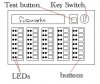
Basically I want to end up with something that looks roughly like this.

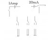
There needs to be: a test circuit carrying 20mA, and that lights all the LEDs for stations with fireworks attached (ie electronic ignighter - therefore no firework = no circuit). A kill switch, to if the key is not on, nothing works. And there will be several stations (how many will depend on cost. I can always upgrade later).
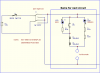
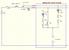
The problem I am having is no matter which way I go, I always end up shorting the two circuits. So the test function works OK, but when I go to fire one station, they all fire because of the short.
How do I get around this?? I have tried a relay to seperate the circuits with a relay, but it didn;t work. I might need a relay for each station??
Is there a way to set it up so that there is a transistor which passes 20mA, but when the station fire button is triggered, it allows 1Amp??? I don't reaaly know.

If anyone can help, I'd really appreciate it. The guy at the local electronic store is more interested in telling me I should use a laptop system, but I am struggling to build this, let alone something that full on!!!
Any ideas???
Attached Images
File Type: jpg schematic_180.jpg (7.2 KB, 784 views)
File Type: jpg diagram_941.jpg (27.6 KB, 738 views)
patrickredmon is offline   Reply With Quote
Old 22nd April 2006, 11:41 AM   (permalink)
Experienced Member
 
mramos1 is a jewel in the roughmramos1 is a jewel in the rough
Default

Can you post the schematic of what you have? That will help everyone help you.
mramos1 is offline   Reply With Quote
Old 22nd April 2006, 12:16 PM   (permalink)
Experienced Member
spuffock has a spectacular aura about
Default

It seems that you only need 2 leds in series and a suitable resistor, say, 470 ohms for a 12v system, also in series, with each firing line. This will limit the current to under 20mA, and the firing key simply shorts out the leds and resistor.
Of course, if you want to run the whole lot via a mile of cheap twin flex, it gets a bit harder to do........
spuffock is offline   Reply With Quote
Old 22nd April 2006, 12:40 PM   (permalink)
Experienced Member
 
eblc1388 is just really niceeblc1388 is just really niceeblc1388 is just really nice
Default

I am offering the following circuit for your consideration.

Assumptions:

a) the firework ignitor don't care about current direction
b) it does not goes off with 15mA current

The key switch reverse the battery polarity between unarm/armed position. When the switch is in unarmed position, the green LED will lights up if there is an ignitor connected and the associate cabling has good continuity. If the connection is bad, the LED goes off. This gives you a continuous indication that the circuit is good.

In this unarm position, pushing the PB has no effect and will not trigger the ignitor because the signal is blocked by the two 1N5404 diodes.

When its time to put the circuit in action, the key switch is selected to "armed". This reversed the battery polarity and now the green LEDs go off and red LEDs turn ON. If the PB is pressed, the ignitor will fire. I like this scheme than the simple firing line scheme because all green LEDs switch to RED meaning circuit is now "HOT".

I have designed in extra safety features to cater for component failure so do not modify the circuit by using only one component or combine the two resistors into one. I can add extra safety measure to cater for reversed 12V battery connection if you so wish.

If you have other questions, please ask.
Attached Images
File Type: png firework.png (8.6 KB, 717 views)
__________________
L.Chung
eblc1388 is offline   Reply With Quote
Old 23rd April 2006, 11:59 AM   (permalink)
New Member
patrickredmon is on a distinguished road
Default

eblc1388, I don't care what anyone says, you deserve the title "Electronics God"!!! That is so basic, but I it seems it will do everything perfectly!!! I am truely speechless....

Thank you so much!!!


BTW - both assumptions are correct. Polarity is no issue, and properly functioning ignighter will not fire with 15 - 20mA.
patrickredmon is offline   Reply With Quote
Old 23rd April 2006, 12:25 PM   (permalink)
Experienced Member
 
eblc1388 is just really niceeblc1388 is just really niceeblc1388 is just really nice
Default

There are still problem(s) with the previous circuit which you are not aware. I will give a slightly "improved" design, which allow future extensions like short circuit detection and current limiting.

What is the DC resistance of an ignitor, measured by a Digital Multimeter? If it is too low, extra electronics for short circuit detection will be difficult.

Do you know if the "professional" console deal with the problem of short circuit effectively?

There is, however, a simple solution. While the console is in "unarmed" mode, one can use a DVM with mV range and measures the voltage across the terminals. A good circuit would give some millivolts and be consistant with the rest of the circuits. A very low reading would requires furthur investigation for possible short circuit.

Edited: Resistor added to cater for external short circuit condition as per Nigel's suggestion.
Attached Images
File Type: png firewk2.png (7.0 KB, 595 views)
__________________
L.Chung
eblc1388 is offline   Reply With Quote
Old 23rd April 2006, 02:03 PM   (permalink)
Super Moderator
 
Nigel Goodwin is a splendid one to beholdNigel Goodwin is a splendid one to beholdNigel Goodwin is a splendid one to beholdNigel Goodwin is a splendid one to beholdNigel Goodwin is a splendid one to beholdNigel Goodwin is a splendid one to beholdNigel Goodwin is a splendid one to behold
Default

Quote:
Originally Posted by eblc1388
Do you know if the "professional" console deal with the problem of short circuit effectively?
How about just adding a low value resistor in series with the PB switch, limiting the current to 1A? - if there's a dead short, and you press the button, it's likely to weld the PB contacts together, a series resistor will prevent it.
__________________
PIC programmer software, and PIC Tutorials at:
http://www.winpicprog.co.uk
Nigel Goodwin is online now   Reply With Quote
Old 23rd April 2006, 02:11 PM   (permalink)
Experienced Member
 
eblc1388 is just really niceeblc1388 is just really niceeblc1388 is just really nice
Default

Quote:
Originally Posted by Nigel Goodwin
How about just adding a low value resistor in series with the PB switch, limiting the current to 1A? - if there's a dead short, and you press the button, it's likely to weld the PB contacts together, a series resistor will prevent it.
Good suggestion. A single 10 ohm resistor placed between key switch and "armed" rail will take care of this.

Above schematic updated to include Nigel's improvement.
__________________
L.Chung
eblc1388 is offline   Reply With Quote
Old 23rd April 2006, 02:14 PM   (permalink)
Super Moderator
 
Nigel Goodwin is a splendid one to beholdNigel Goodwin is a splendid one to beholdNigel Goodwin is a splendid one to beholdNigel Goodwin is a splendid one to beholdNigel Goodwin is a splendid one to beholdNigel Goodwin is a splendid one to beholdNigel Goodwin is a splendid one to behold
Default

Quote:
Originally Posted by eblc1388
Quote:
Originally Posted by Nigel Goodwin
How about just adding a low value resistor in series with the PB switch, limiting the current to 1A? - if there's a dead short, and you press the button, it's likely to weld the PB contacts together, a series resistor will prevent it.
Good suggestion. A single 10 ohm resistor placed between key switch and "armed" rail will take care of this.
Don't forget, this needs to be a high wattage wirewound type!.

EDIT: Sudden extra thought! - how about using a charged electrolytic to fire the ignitor (obviously depending on the power it requires), this would obviate the need for big wirewound resistors. You could have a far higher value resistor charging the capacitor.
__________________
PIC programmer software, and PIC Tutorials at:
http://www.winpicprog.co.uk
Nigel Goodwin is online now   Reply With Quote
Old 23rd April 2006, 02:21 PM   (permalink)
Experienced Member
 
eblc1388 is just really niceeblc1388 is just really niceeblc1388 is just really nice
Default

Quote:
Originally Posted by Nigel Goodwin
EDIT: Sudden extra thought! - how about using a charged electrolytic to fire the ignitor (obviously depending on the power it requires), this would obviate the need for big wirewound resistors. You could have a far higher value resistor charging the capacitor.
The high current from the cap discharge could weld the contact also.
__________________
L.Chung
eblc1388 is offline   Reply With Quote
Old 23rd April 2006, 02:23 PM   (permalink)
Super Moderator
 
Nigel Goodwin is a splendid one to beholdNigel Goodwin is a splendid one to beholdNigel Goodwin is a splendid one to beholdNigel Goodwin is a splendid one to beholdNigel Goodwin is a splendid one to beholdNigel Goodwin is a splendid one to beholdNigel Goodwin is a splendid one to behold
Default

Quote:
Originally Posted by eblc1388
Quote:
Originally Posted by Nigel Goodwin
EDIT: Sudden extra thought! - how about using a charged electrolytic to fire the ignitor (obviously depending on the power it requires), this would obviate the need for big wirewound resistors. You could have a far higher value resistor charging the capacitor.
The high current from the cap discharge could weld the contact also.
No, you still have the 10 ohm, but it can be a small one now - as the current isn't sustained if you hold the button down.
__________________
PIC programmer software, and PIC Tutorials at:
http://www.winpicprog.co.uk
Nigel Goodwin is online now   Reply With Quote
Old 24th April 2006, 03:25 AM   (permalink)
New Member
patrickredmon is on a distinguished road
Default

Wow guys - thanks for your input.
I am fast approaching the limit of my understanding on this...
The resistance is between 1.8 and 2.2 ohms (depending on wire length). I believe that 12V is the usual voltage.
I believe there is an inbuilt short test. Before connecting any ignighter you simply switch it onto test mode. I any LED's light up, you have a short. That's how the pro system does it. I would assume this is the same. Would this rule out the need for short circuit detection?? I have never seen a multimeter built into a firing system
DVM = digital voltometer?? Sorry - not sure if I understand.
Not sure if I am on the right track here, but would the idea of an electrolytic take some time to charge?? This might be a pain. If it's the only way, I'll take it though!
BTW, when the firework fires, the circuit is broken. The ignighters are basically a fuse, with black powder on them so when the current is sufficient, it goes bang. This usually takes a fraction of a second, so I don't think heating will be an issue.
I also plan to break the wiring sections into groups of 10 for ease of spacing, but also to limit heating. Does this sound fair???
Can someone give me part numbers for the components. I want to make sure I get the right stuff!!!

Once again guys, thanks for your help!! It is amazing!!
patrickredmon is offline   Reply With Quote
Old 24th April 2006, 08:08 AM   (permalink)
Experienced Member
 
eblc1388 is just really niceeblc1388 is just really niceeblc1388 is just really nice
Default

Quote:
Originally Posted by patrickredmon
The resistance is between 1.8 and 2.2 ohms (depending on wire length). I believe that 12V is the usual voltage.
I believe there is an inbuilt short test. Before connecting any ignighter you simply switch it onto test mode. I any LED's light up, you have a short. That's how the pro system does it. I would assume this is the same. Would this rule out the need for short circuit detection?? I have never seen a multimeter built into a firing system
No. I was advising to use a handheld DVM(digital voltmeter), setting to the mV range to measure across each connection at the console. This can be done circuit by circuit during connection or all at once after all the circuits are connected. With current of 15mA to 20mA flowing in the circuit via the green LED and resistors, a healthy circuit(good ignitor and no cable shorts) will develope about 30 to 40mV across the terminals, which shows up clearly on the meter display. A meter reading of under 20mV would indicate something not quite right and furthur investigation is required. Once you have confirmed there is no shorts, that's it. The meter can be removed.

This does not cater for the possibility that one of the circuits goes into short-circuit after connection to the console and before actual firing. But usually, a open-circuited situation(which is monitored by the green LED) is many times more likely to happen than a short circuit.

Quote:
Originally Posted by patrickredmon
I also plan to break the wiring sections into groups of 10 for ease of spacing, but also to limit heating. Does this sound fair???
I agree that there is no possible heating problem. The 10 ohm resistor is there to protect against short circuit. It will barely heat up. The other components like LEDs and resistors generate very little heat to cause any concern.

Quote:
Originally Posted by patrickredmon
Can someone give me part numbers for the components. I want to make sure I get the right stuff!!!
You need to fill in the "country" information in your profile or tell us which component shops you have access to.
__________________
L.Chung
eblc1388 is offline   Reply With Quote
Old 24th April 2006, 09:43 AM   (permalink)
New Member
patrickredmon is on a distinguished road
Default

I'm in Australia. The supplier I know is www.jaycar.com.au
patrickredmon is offline   Reply With Quote
Old 24th April 2006, 06:00 PM   (permalink)
Experienced Member
 
eblc1388 is just really niceeblc1388 is just really niceeblc1388 is just really nice
Default

I have checked the Jaycar cataloge and can recommend the following items:

SL2610 Red LED 5mm
SL2612 Green LED 5mm
RR0564 470R 1/2W resistor (pack of eight)
RR3351 8.2 Ohm 10W resistor (instead of 10 ohm in schematic)
SZ2025 Fuse Holder
SF2107 Ceramic 5x20mm fuse 2.5A
ST0570 Toggle switch (for main power ON/OFF)
SP0716 Push Button

No suitable keyswitch was found. The circuit requires a SPDT types but all Jaycar's stock is SPST or DPST. Current rating required is about 2 to 3A, 12V. You have to try other venders or ask in forum.

Please go to Jaycar's website and check the part number, size and the quantity required to build your console. You also need to find suitable connection terminals.
__________________
L.Chung
eblc1388 is offline   Reply With Quote
Reply

Bookmarks

Thread Tools
Display Modes


All times are GMT. The time now is 07:53 PM.


Electronic Circuits  |  Radio Controlled
Powered by vBulletin® Version 3.7.0
Copyright ©2000 - 2008, Jelsoft Enterprises Ltd.