Continue to Site

Welcome to our site!

Electro Tech is an online community (with over 170,000 members) who enjoy talking about and building electronic circuits, projects and gadgets. To participate you need to register. Registration is free. Click here to register now.

  • Welcome to our site! Electro Tech is an online community (with over 170,000 members) who enjoy talking about and building electronic circuits, projects and gadgets. To participate you need to register. Registration is free. Click here to register now.

Solenoid valve (version 2)

Status
Not open for further replies.

leonel

New Member
Hi.
I have one (big) problem...
It's the follwing!
I want to control (open / close) a solenoid valve (latching model).
To do this i have to invert polarity in the coil (minimum energizing time is 20ms)
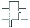
I have a +12V signal - in the positive transition i want to close my valve and in the negative transition i want to open my valve. So what i have to do is shown in the figure.
Why i choose a valve latching model? It's because my system is supplied by an +12V battery.
Please help me in a circuit to do this...
Regards
 

Attachments

  • sem_t_tulo.jpg
    sem_t_tulo.jpg
    15.8 KB · Views: 1,244
what are you using to drive this solenoid?
I would think you'd be able to get away with a DPDT momentary switch that switches the polarity to the solenoid.
 
This circuit does not use the latching property of the solonoid. Some power could be saved with a pulsing technique, but that was not a design parameter. This circuit will handle up to 250 mA solonoid current.
 

Attachments

  • solonoid_driver.gif
    solonoid_driver.gif
    16.3 KB · Views: 1,221
A Bit Low Tech but try it.
Uses Standard Automotive Cube Relays.
 

Attachments

  • solenoid_flipper.gif
    solenoid_flipper.gif
    8.8 KB · Views: 1,121
HERE IS ANOTHER
 

Attachments

  • motor_reverse_relays_push.gif
    motor_reverse_relays_push.gif
    10.7 KB · Views: 1,093
Sorry to be out so long...
It can't be with switches, because what i have is a +12V, produced by a PIR sensor and a timer.
The PIR sensor is there to detect motion and when mention is detected i have to open my valve (water starts running) and when stops detecting my valve closes (water stops running). I have to suplly all system with a 12V battery. Power saving should be a design parameter (that's way i use latching property)
 
leonel said:
Sorry to be out so long...
It can't be with switches, because what i have is a +12V, produced by a PIR sensor and a timer.
The PIR sensor is there to detect motion and when mention is detected i have to open my valve (water starts running) and when stops detecting my valve closes (water stops running). I have to suplly all system with a 12V battery. Power saving should be a design parameter (that's way i use latching property)
I haven't tested this, or even simulated the entire circuit, but I think it should work. I did do a timing diagram, so it wasn't pulled out of a hat, and I simulated the H-bridge portion.
Tell us how much current the solenoid requires and I can recommend MOSFETs.
It will draw no power except during about 30ms each time the solenoid switches, and then the only significant power dissipated is in the solenoid.
You can add 10k each across D2 and D4 if damped oscillation (ringing) is a problem for some reason (which I doubt).
 

Attachments

  • latching_solenoid_dvr2.png
    latching_solenoid_dvr2.png
    22.3 KB · Views: 1,028
Here is another circuit. If you use CMOS 555s, the standby current will be minimal. The one shot time is 15mS which I estimated would be sufficient to flip the solonoid.
 

Attachments

  • solonoid_driver_126.gif
    solonoid_driver_126.gif
    16.1 KB · Views: 1,021
Hmmm a water valve?
 

Attachments

  • water_level_controller.doc
    36 KB · Views: 251
I need 20ms to switch my valve.
I did a similar circuit Ron advise but i will test Ron H. circuit.
Alse i will test Russlk circuit then i'll tell the result.
Thank's
 
Hi.
I've tested Ron H circuit and works fine. The problem his that i do not have mosfets in stock. Can i do this with transistors? I tried with BC546 and didn't work... The corrent i need is +-40mA and an energizing time of about 20ms.
Thank you.
 
Cheap simple H-bridge driver IC, the TC4424

I've used the TC4424, it's only an 8pin DIP and can handle short bursts of current. Works nice in HO trains DCC

https://www.robotroom.com/HBridge.html

Need lots of current an L298 dual h-bridge and the outputs can be combined to provide scads of current.

I've used the TC4424 (Armadillo) and the L298 (Emu) on my web page.
 
leonel said:
Hi.
I've tested Ron H circuit and works fine. The problem his that i do not have mosfets in stock. Can i do this with transistors? I tried with BC546 and didn't work... The corrent i need is +-40mA and an energizing time of about 20ms.
Thank you.
Here's a schematic to supplement Russ' reply. You can use any transistors that can easily handle 40ma. Just be sure to use PNPs for the upper transistors and NPNs for the lower ones.
 

Attachments

  • latching_solenoid_dvr_bipolar1.png
    latching_solenoid_dvr_bipolar1.png
    18.7 KB · Views: 458
leonel said:
just one question...
I have to use both PNP and NPN or i can only use the two NPN?
You can use 4 NPNs, and save two resistors. The solenoid voltage drive will be reduced by about 0.8 volts, but should still work OK.

EDIT: Added diodes and resistors from base to emitter on the upper transistors to avoid b-e breakdown possibilities when the flyback pulse occurs.
 

Attachments

  • latching_solenoid_dvr_npn2.png
    latching_solenoid_dvr_npn2.png
    18.6 KB · Views: 387
I tried again and didn´t work.
There are two thinks i'm not doing:
1st: i'm not putting diodo zener
2nd: i don't know
 
Status
Not open for further replies.

Latest threads

Back
Top