Electronic Circuits and Projects Forum


h bridge driver circuit

12 Last »
  1. #1
    jrz126 jrz126 is offline

    h bridge driver circuit

    Hey all,
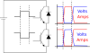
    I've got a project that involves some pretty high voltage motors and I need a way to drive them.
    I found this schematic here http://www.armory.com/~rstevew/Publi...d/h-bridge.htm

    Is there something better available? (my motor is rated at 42V and 3.4A rms)
    Jeff
    To the optimist, the glass is half full.
    To the pessimist, the glass is half empty.
    To the engineer, the glass is twice as big as it needs to be.

  2. #2
    theinfamousbob theinfamousbob is offline
    I've never used a MOSFET H-bridge but do know about H-bridges in general.

    Remember that sudden changes in direction can cause a voltage swing of 2x the supply voltage, which could kill parts.

    Other than that, the circuit looks alright. Just make sure the MOSFETs are high enough power, along with the other components.

    -Infamous
    0

  3. #3
    Styx Styx is offline
    Quote Originally Posted by theinfamousbob
    I've never used a MOSFET H-bridge but do know about H-bridges in general.

    Remember that sudden changes in direction can cause a voltage swing of 2x the supply voltage, which could kill parts.

    Other than that, the circuit looks alright. Just make sure the MOSFETs are high enough power, along with the other components.

    -Infamous
    The so-called regenerative effect of a 4-quadrant inverter. Yup you will need to dissipate that power somewhere. In big industrial drives this gets re-inverted onto the national grib, but hear I would suggest a braking cct.

    a DC-link hysteresis-controlled chopper cct to switch in a low-ohmic, high power resistor across the DC-link to "dump" the excess charge.


    Back to main question. 42 volt high
    Well one thing I would say the intrinsic diode of MOSFET's are actually extreamly shite when used in H-bridges.
    For low-power stuff (1W-5W) they are ok, but for more power, the mis-match in switching times starts to become a major hindrance in ensuring no switching shoot-throughs.

    My only concern with this design is to do with your operating voltage. This H-bridge has been setup to run at 12V, as a result they can use the cheaky pull-up resistors to turn on/off the upper FET's

    You are not going to have that luxury with working at 42volts.
    You are going to have to have an isolated Gate-drive for (at least) the upper two FET's, giving them a floatingh supply to allow the gate-source to be switched local to this isolated supply.

    Newport do some very good (small as well) isolated DCC converters which I would recomend for hte design of the gate-drive.
    It doesn't have to be fancy

    DCC converter for isolated/floating rails
    Opto to isolate command signal
    FET-driver chip

    Whith working at a higher voltage the speed at which you turn the FET's on is going to become more important. The problem with this 12V design is it uses a 10k to turn OFF/ON which is bloody slow. You are going to want to turn these FET's on alot faster so a gate resistor in the order of 100R is needed (but check datasheets)

    Also you might want to put dedicated interlocks between fuiring an upper & lower device to really rule out any switching shoot-through
    0
    Nothing is impossible.
    Once a problem is realised, the rest is just details


  4. Thread Starter #4
    jrz126 jrz126 is offline
    Hmmm...guess this is going to be more difficult than I thought. The motors are rated for 42 volts, but I dont have to run them at that voltage, I think I'll just give 12V a try and see if it is sufficient. As long as it can handle the current (roughly 5-6 amps when stalled at 12V) I should be ok.

    Now I just have to find some decent P channel mosfets.
    0
    Jeff
    To the optimist, the glass is half full.
    To the pessimist, the glass is half empty.
    To the engineer, the glass is twice as big as it needs to be.

  5. #5
    Nigel Goodwin Nigel Goodwin is offline
    Super Moderator
    Quote Originally Posted by jrz126
    Hmmm...guess this is going to be more difficult than I thought. The motors are rated for 42 volts, but I dont have to run them at that voltage, I think I'll just give 12V a try and see if it is sufficient. As long as it can handle the current (roughly 5-6 amps when stalled at 12V) I should be ok.
    What sort of power do you need from the motors? - running a 42V motor off only 12V is going to give SERIOUSLY little power, assuming it works at all?.
    0
    PIC programmer software, and PIC Tutorials at:
    http://www.winpicprog.co.uk

  6. Thread Starter #6
    jrz126 jrz126 is offline
    I'm trying to make a simple CNC router/plotter. The motor is originally off of a 1 dimensional plotter (the pens would move back and forth on a slide and the paper would be fed by another motor).

    I still have the slide and I'm planning on using it for my router. It's also geared down pretty good, so hopefully I have enough torque to move it.

    Also, I found this schematic at the same site. Which might solve my P channel mosfet situation.

    but it looks like it requires 4 PWM signals. Can I just feed the PWM signal into A and an inverter IC, then take the inverted PWM signal and put it on Input C? I dont really see a problem with this as long as I'm using a high speed inverter, but I'm probably wrong.
    I'd also need to come up with some directional control circuitry since I'm only going to have 1 pwm signal available.
    0
    Jeff
    To the optimist, the glass is half full.
    To the pessimist, the glass is half empty.
    To the engineer, the glass is twice as big as it needs to be.

  7. #7
    Optikon Optikon is offline
    Quote Originally Posted by jrz126
    I'm trying to make a simple CNC router/plotter. The motor is originally off of a 1 dimensional plotter (the pens would move back and forth on a slide and the paper would be fed by another motor).

    I still have the slide and I'm planning on using it for my router. It's also geared down pretty good, so hopefully I have enough torque to move it.

    Also, I found this schematic at the same site. Which might solve my P channel mosfet situation.

    but it looks like it requires 4 PWM signals. Can I just feed the PWM signal into A and an inverter IC, then take the inverted PWM signal and put it on Input C? I dont really see a problem with this as long as I'm using a high speed inverter, but I'm probably wrong.
    I'd also need to come up with some directional control circuitry since I'm only going to have 1 pwm signal available.
    Consider also:

    Solutions for shoot-through:
    1) Program some dead-time for the FET switching. If your application can tolerate this, this is easy and it is done ALL the time.
    2) Place inductors in series with the FETS. I've seen this done is power applications that limit the shoot through based on limiting the rate of change of drain current.

    Also, the original design is a suitable & typical H-bridge, provided you follow the advice already given - it just needs upgraded parts (FETS caps, diodes & driver circuits) The P-channel mosfet being in there is not a problem. You can find a suitable one from lots of vendors (fairchild for sure).

    Be careful to pay attention to the ripple current of the capacitors you place in there so as not to exceed their specs. Also make sure that your gate driver can actually provide enough transient current to switch the bridge as needed. This can be a suprisingly large amount! (i.e. a CMOS logic part might not do it..)


    I think everything you've shown so far is a workable topology. You could put together your version of it with parts and simulate it with an L-R load as a motor model.
    0

  8. #8
    Styx Styx is offline
    Quote Originally Posted by Optikon
    2) Place inductors in series with the FETS. I've seen this done is power applications that limit the shoot through based on limiting the rate of change of drain current.
    :shock:
    You sure about this? The whole purpose of a voltage-source inverter is to reduce the inductance to the H-bridge to provide a pure voltage-source to the load.

    Also the extra inductance will increase device turn-off overshoot which in turn increase switching losses?

    The addition of extra inductance in anything BUT the load (or before the DC-link capacitor when supplied from a rectifier) is counter-intuitive to a voltage-source inverter

    As I stated, the addition of dead-time to ensure switching-shoot-throughs are avoided is the best solution


    W.r.t. the topology posted, I am a bit confused to why the high-pass filter caps are at the gate of the FET's ?? Are you doing this to provide capacitve isolation to allow the switching of the FET's? such a scheme will not provide anywhere near enough gate-current to allow the FET's to switch at a decent (let alone recomended ) speed
    0
    Nothing is impossible.
    Once a problem is realised, the rest is just details


  9. Thread Starter #9
    jrz126 jrz126 is offline
    1) Program some dead-time for the FET switching. If your application can tolerate this, this is easy and it is done ALL the time.
    2) Place inductors in series with the FETS. I've seen this done is power applications that limit the shoot through based on limiting the rate of change of drain current.
    Is this dead time for when I am switching directions? or just turning on each individual fet (with the PWM).
    and what exactly is this shoot through current?
    0
    Jeff
    To the optimist, the glass is half full.
    To the pessimist, the glass is half empty.
    To the engineer, the glass is twice as big as it needs to be.

  10. #10
    Styx Styx is offline
    A H-bridge can be broken down into legs

    For this single phase inverter

    LEFT LEG is the upper and lower FET on the left (that are tied to D1 and D4)

    RIGHT LEG is the upper and lower FET on the right (that are tied to D2 and D3)


    The one thing that you must NEVER do with a voltage source inverter (that this is) is provide a short-circuit across the supply.

    That can occur if you turn both devices on in a LEG, VERY BAD!!!!!!! more then BAD, it is dead FET's, IGBT's, GTO's, BJT's...

    Such an event is called a Shoot-through


    There are two types of shoot-throughs

    1) Commanded. You have no purpose EVER to turn an UPPER and a LOWER Switch in the same LEG on EVER!!!, but if there is a problem in your control (something you overlooked) you could turn both on. This situation is very bad

    2) switching: In a phase LEG the UPPER and LOWER switches are fed the compliment PWM signal (so they are never commanded ON at the same time). However, switches do not turn-on/off instantaniously, it take time

    IF you command the upper to turn-off and the lower to turn-on at the same time (or vica verca) then there will be instances where you have provided a path for current to flow through a leg BAD!!!!!!!! the current flowing will not be as bad as if it was a commanded shoot-through (since the devices are transitioning between states) but the killer is, that the switches in this condition are in their active region, big volts and big amps POP!!!!! too much power BAD!!!!!!


    To get around this drive designers add a time delay between the upper and lower device (dead-time, interlocks...) such that this cannot happen (well it still can but at extreame temp and other situations)
    0
    Nothing is impossible.
    Once a problem is realised, the rest is just details


12 Last »
Tags
Electronic Circuits  |  Learning Electronics

Join our community with over 100,000 Members! It's free, easy and when you're logged in you have many more features! Click to register.
Page Time: 0.12161 seconds      Memory: 7,700 KB      Queries: 15      Templates: 0