hi Roman,
In case you have not already got it, a free filter design calc.
http://focus.ti.com/docs/toolsw/fold...filterpro.html
Hi, I'm making a "precision" 1kHz sine wave generator, using a PIC 16F628 and 20MHz xtal.
Goals;
1. Sine freq 1000Hz high freq accuracy, xtal locked
2. Sine amplitude "exactly" 2v p/p set by 5v regulator and trimpot good enough
3. Sine distortion as low as possible using simple external filter parts
4. Low-ish output impedance to connect to audio amp inputs etc
5. Minimum parts as it is an open source project for everyone
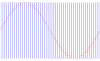
The xtal has been trimmed to 20Mhz better than 1PPM, and the 1kHz sine is generated by PIC PWM with 50 entries in a jitter-free sine table at exactly 20uS per entry. The sine table I made in Excel is shown below.
The PWM has a resolution of 100 steps, and sine table runs an amplitude of 73 PWM steps from PWM of 14 to PWM of 86. It is equally distributed +/- from PWM 50 so there is no distortion and each sine sample has been rounded the correct direction so amplitude error in any sine PWM sample is less than about 0.68% of the total amplitude.
The idea is that since the PIC and mathematical sine tabe already produces excellent frequency and good basic sine shape (ie the hard stuff ie done), so that addition of a simple passive filter will be all that is needed.
The PIC sine part is working perfectly and it generates a sine from the 50 samples with an exact freq of 1kHz (around 1000.0000 Hz +/- 0.0005Hz).
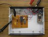
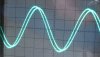
The PIC hardware is simplicity itself at this point, just the 0v-5v PWM coming out the PIC pin, and I tacked a trimpot and 0.22uF cap RC filter on that for testing.
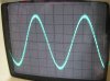
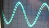
The trimpot was adjusted to take out the bulk of the hash without reducing the amplitude or changing the shape of the sine. RC filter as seen in the photos below; 482 ohms, 0.221uF, sine amplitude 3v p/p.
Now the question!
I have lots of parts avaliable including toroid formers and quality caps of different types, cap and inductance meters etc, and a 'scope, but no proper distortion measuring equipment. What would be the best simple passive filter to attach to this PWM output to give the desired "low distortion" result at 1kHz 2v p/p?
My filter design knowlege is poor, limited to googling "Chebychase filter calculator" on some rare occasions... (grin)
Last edited by Mr RB; 9th June 2011 at 01:16 PM.
Roman Black - PICs and electronics. Author of BTc PIC-sound encoder, Shift1-LCD project, the TalkBotBrain talking PIC controller, LiniStepper open-source microstepping motor driver, the Black Regulator 2-transistor SMPS, and probably some other stuff; www.RomanBlack.com
hi Roman,
In case you have not already got it, a free filter design calc.
http://focus.ti.com/docs/toolsw/fold...filterpro.html
Eric " Good enough is Perfect "
I will NOT answer PM's requesting technical help, please use the Forum
"Nigels Asm tutorials:" www.winpicprog.co.uk/
"Ian Rogers 'C' conversion of Nigels Asm tutorials:" http://www.electro-tech-online.com/c...torials-c.html
Thanks I'll look into that. But even with a filter calculator I'm still likely to enter the wrong values or something.
It will be easy enough for me to filter that output a bit more to make it look perfect on the 'scope but I really would like some input from someone with experience, on a filter that will guarantee a low distortion output given the present state of the circuit.
Roman Black - PICs and electronics. Author of BTc PIC-sound encoder, Shift1-LCD project, the TalkBotBrain talking PIC controller, LiniStepper open-source microstepping motor driver, the Black Regulator 2-transistor SMPS, and probably some other stuff; www.RomanBlack.com
Active filter or passive filter, you need a filter. You need to remove all noise above 1khz with out effecting the 1khz much.
Add a 1khz low pass filter. If you are off in the values and you make a 2khz filter it will work just fine. If you make a 500hz filter the 1k will be down some. So the frequency is not critical but better if you are a little high.
The goal is to pass the 1k and kill the 50khz and its harmonics.
Hi there MrRB,
I have found a bandpass filter works pretty well for filtering even a square wave into a nice sine wave, so with your pulsed wave it should work even better.
Maybe an inductor / capacitor filter if you have the parts.
I know you have already done some of the basic digital ground work, but i can offer a few extra hints if you care to reexamine your approach just a little bit.
Point1:
A sine pattern is symmetrical in a few different ways. As i am sure you know, it has the same shape above zero as below zero. It also has the same shape over a 90 degree angle, except in reverse: 0 to 90 is the same as 90 to 180 except the amplitudes are reversed. These two symmetries alone mean that we really only have to store the pattern for the sine from 0 to 90 degrees, changing only the order we look up the values in for the 'reversed' segments. What this means overall is with the same memory space we can get a higher resolution pattern.
Point2:
We dont really have to store the pattern itself, if we want to we can generate the pattern on power up and store the calculated values in 'ram' space. This can make up for differing power supply levels or whatever if needed, or just used to get a good pattern without storing everything beforehand.
Point3:
The levels near the peaks of the sine are more important from a distortion point of view than the levels near the zero points of the sine wave. This means accuracy near the peaks is much more important than near the zero cross areas, and so more attention should be paid for the pattern near the peaks.
Point4:
With point 3 in mind, dithering might help the distortion near the peaks, if you care to get into that of course.
It might be interesting to run a harmonic analysis on your pattern to see what the total harmonic distortion is before and after the proposed filter. Do you have the actual numbers for the pattern available?
Last edited by MrAl; 9th June 2011 at 01:37 PM.
One test is worth a thousand expert opinions, but one expert specification is worth a thousand tests.
If i miss something you posted or something you think is important, feel free to PM me.
My very low distortion (0.002%) sine-wave generator circuit starts with a stepped sine-wave made from a CD4018. It uses 3 resistors to make a sine-wave with 10 steps. It is filtered with a switched-capacitor lowpass filter IC plus a high frequency Sallen and Key lowpass filter to remove the clock frequency.
I tried to make it have a voltage-controlled frequency with a CD4046 phase-locked-loop IC but the PLL oscillator has jitter which increases the distortion a lot.
Uncle $crooge
Ronsimpson, cool, so if I just make a LC filter with a couple of poles set to 2kHz that should get a good result without causing any shape distortion of the sine wave? It's 3v now and I need 2v p/p final so there is a bit of headroom to play with.
MrAl, thanks for the tips. I did a sine generator before where the table was 1 quadrant and used inversion and doubling to get the full sine wave. The limitation in this case was the 20MHz PIC runs at 5 MIPS so the 50 entry sine table has only 20uS (100 instructions) per sine entry and per PWM cycle. There's no time for any niceties like smoothing with a PIC 16F.
I'm not too worried about the per-entry sine amplitude distortion, even the first crude RC filter has smoothed out the 0.68% max amplitude errors in any one entry, you can see the difference in the Excel sine (with the little amplitude errors) vs the RC filtered sine where those little errors are basically gone due to the overall integration.
Code :Here are the 50 PWM sine table entries; 50 55 59 63 67 71 75 78 80 83 84 85 86 86 85 84 83 80 78 75 71 67 63 59 55 50 45 41 37 33 29 25 22 20 17 16 15 14 14 15 16 17 20 22 25 29 33 37 41 45
I expect the distortion on these will be a bit high due to the low PWM resolution of 73 PWM steps for the whole sine wave. Again this is mainly a limitation of the PIC 16F, I can go to a 18F series at 10 MIPS and pretty much double PWM resolution and/or sine entries, but I would like to keep this to a 16F628 for now as that will be of use to hobbyists.
Audioguru, thanks for the info. Interesting that you can get an output that low in distortion from a 10 step original wave! I take it that is 5 steps per half wave?
Last edited by Mr RB; 9th June 2011 at 01:58 PM.
Roman Black - PICs and electronics. Author of BTc PIC-sound encoder, Shift1-LCD project, the TalkBotBrain talking PIC controller, LiniStepper open-source microstepping motor driver, the Black Regulator 2-transistor SMPS, and probably some other stuff; www.RomanBlack.com
Yes the original wave has 5 steps for each half-cycle. An 8th order switched capacitor butterworth lowpass filter IC removes harmonics very well. You can feed a square-wave to one and get a low distortion sine-wave output (with a small amount of clock frequency that is 100 times the sine-wave frequency).
Uncle $crooge
Hi again MrRB,
Ok let me make sure i understand your pulse generation scheme here...
For the first pulse which is 50, you generate a '1' output for 50 instruction cycles, then output a '0' for 50 more instr cycles, then
for the second pulse which is 55 you output a '1' for 55 instr cycles, then output a '0' for 45 more instr cycles, then
for the third pulse which is 59 you output a '1' for 59 instr cycles, then output a '0' for 41 more instr cycles, then
etc., etc.,
until you get to the last and then repeat.
So in general you output a '1' for the table entry and then a '0' for 100 minus the table entry.
Is this correct?
The reason i ask is because i want to make sure i have the right pattern to analyze. We can then compare the harmonic distortion output using various filters and see which one is best.
Also, what is the value of your test resistance and capacitance for the test filter shown in the picture, and what is the amplitude of the sine in the scope picture (scope vertical main grid scale)?
Also, what is the minimum output resistive load you wish to be able to apply without losing too much amplitude? Is 10k ok or do you need more like 1k or 600 ohms?
Last edited by MrAl; 9th June 2011 at 06:35 PM.
One test is worth a thousand expert opinions, but one expert specification is worth a thousand tests.
If i miss something you posted or something you think is important, feel free to PM me.
Agustín Tomás
In theory, there is no difference between theory and practice. In practice, however, there is.
| Tags |
| Similar Threads | ||||
| Thread | Starter | Forum | Replies | Last Post |
| 20mhz-40mhz sine osilator please help | matbymay | General Electronics Chat | 26 | 26th August 2009, 06:09 PM |
| Someone Please Help me!!! | Fonzz | Electronic Projects Design/Ideas/Reviews | 3 | 15th January 2003, 06:37 AM |
| Soundcard modification - please help | daveppeters | General Electronics Chat | 1 | 9th January 2003, 04:00 AM |
| Please help me with this simple circuit. i cant do it alone! | nate | Electronic Projects Design/Ideas/Reviews | 10 | 23rd December 2002, 01:31 PM |
| PLease HElp Me | farq2598 | Electronic Projects Design/Ideas/Reviews | 4 | 14th December 2002, 03:22 PM |