Electro Tech is an online community (with over 170,000 members) who enjoy talking about and building electronic circuits, projects and gadgets. To participate you need to register. Registration is free. Click here to register now.
Welcome to our site! Electro Tech is an online community (with over 170,000 members) who enjoy talking about and building electronic circuits, projects and gadgets. To participate you need to register. Registration is free. Click here to register now.
Can someone tell me ( or direct me to a link to show) how hard it would be to convert the relay in this design to a triac? It switches a 120v Ni-chrome wire that is 60ohms. Thanks for any help you can offer.
You've chopped enough off the diagram to make the uncertainty excessive. Un-isolating a high power control circuit requires knowledge of the ground circuits.
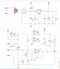
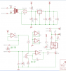
Your right i apologize. The ic powers off of a 12v transformer. However there is a 120v neutral and line onboard that feeds a 12v voltage regulator. Here is the proposed circuit. It's still a work in progress.
Method 1) Connect the 120 volt neutral to the circuit ground, then use T1 to send current through a resistor to the gate of a triac and connect one end of the nichrome to the 120 circuit and the other end to the anode of the triac. The third terminal of the triac goes to ground. The collector of T1 goes to the +12 supply.
method 2) Don't connect the 120 neutral to the circuit ground. Have T1 drive an opto-isolator and have that drives a triac. The nichrome power circuit will stand seperate from your primary circuitry, connected only by a light beam inside the opto-isolator.
method 3) Use the relay to send +12 to a resistor, to a triac as in method 1
method 4) Use the relay to send +12 to an opto-isolator to drive a triac as in method 2.
No matter which method, you must use a small inductor in series with the nichrome to keep the inrush current from frying the triac.
I'd recommend method 2 over the others and I'd strongly discourage using method 1 because it removes the isolation between the DC and AC sides which can increase the risk of a shock.
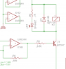
Use the following schematic, I found on a French site. The transistor is the same as the one currently used in your circuit. The series resistor (R2) needs to be increased to 1k because you're using a higher voltage. D1 (your circuit) can be placed in series with R2 (this circuit). **broken link removed** Electronique - Théorie - Triac
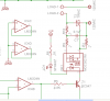
Thanks guys. How this look? I kinda improvised with the MOC3021 Datasheet. Also i have no clue as to the values of the R9,R10 and R3. I'm not sure on which triac to use either. i was thinking a T2500D https://www.electro-tech-online.com/custompdfs/2010/04/T2500-DPDF.pdf but i am open for suggestions, as long as i can get it from digikey.
You've connected the opto-coupler and TRIAC correctly.
The TRIAC you've selected is fine as long as the current drawn by the load is <6A.
Do you know that the LM358 is exactly the same as the LM324 but is only two comparators and as you only need two you could save some space on the PCB and drilling a few holes?
This site uses cookies to help personalise content, tailor your experience and to keep you logged in if you register.
By continuing to use this site, you are consenting to our use of cookies.