Continue to Site

Welcome to our site!

Electro Tech is an online community (with over 170,000 members) who enjoy talking about and building electronic circuits, projects and gadgets. To participate you need to register. Registration is free. Click here to register now.

  • Welcome to our site! Electro Tech is an online community (with over 170,000 members) who enjoy talking about and building electronic circuits, projects and gadgets. To participate you need to register. Registration is free. Click here to register now.

Valentines Day Project for my girlfriend

Status
Not open for further replies.

ThermalRunaway

New Member
Hi all,

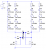
A quick Electronic Design I did for my girlfriend this Valentines Day, 2010. It's just a real simple multivibrator circuit, with the Q and !Q lines fed to a couple of output FETs.

Check it out here:

 
Last edited by a moderator:
Lucky girl. I like that you have the electronics exposed, not hidden on the other side :)
 
@Superfrog...

The PCB is powered by 12V, which is in turn derived from a cheap DC mains adaptor. I toyed with the idea of battery power, but decided against it because my girlfriend is the sentimental sort who'll probably want it turned on all the time, as a sort of decoration. I worked out the length of time that various battery types would power the decoration for, and it turned out to be pretty pointless. I'd need a lot of batteries to power this thing for any useful length of time!

@BrownOut...

I thought about mounting the components on the other side actually, and even considered mounting it all in some kind of enclosure to hide away the internals. But finally I decided that the exposed electronics added to the personality of it. :)

Brian
 
Last edited:
I probably would've used wood for the LEDs and made the circuit on a small PCB, veroboard or just drilled holes through the board and wired the components together with enameled wire.

The circuit could be simplified to use just two transistors and the LEDS connected in series strings of four or even five depending on the forward voltage and threshold of the MOSFETs.


Here's an example.

The LEDs models are red with a Vf of about 1.8V.

I hope the MOSFETs are included LTSpice's default model set, if not just change them with similar ones.

EDIT:
If too many LEDs are connected in series, the voltage drop will mean the MOSFETs won't have a high enough gate voltage to turn on. The circuit below will be fine as drawn with red LEDs. If you want to connect five in series or use a non-logic level MOSFET, the LEDs and series resistor can be bypasses by 10k which will provide a higher gate voltage.
 

Attachments

  • MOSFET Astable.PNG
    MOSFET Astable.PNG
    7.3 KB · Views: 999
  • MOSFET Astable.asc
    3.4 KB · Views: 413
Last edited:
Hi Hero999,

I'm not sure I agree with the method of connecting LEDs in series, I tend to prefer a separate current limiting resistor for each device. However, in practice I wouldn't be surprised if your suggestion turned out to be reliable over many years. It's probably just me being too pedantic with it.

With regard to your MOSFET design - yes that's definitely a much more efficient design indeed. Thanks very much for that. On another forum I mentioned that I did briefly experiment with this, and I can't remember now why I couldn't get it to work, but I think you were probably right with your suggestion about the connection of the RC components. I probably got those wrong.

Thanks again for your suggestions! Version 2?? :)

@vmsa:

Thanks!

Brian
 
There's nothing wrong with connecting LEDs in series, it saves power by reducing the current consumption by a factor of four.

You shouldn't connect LEDs in parallel without separate series resistors because they all will have slightly different forward voltages so the current won't be shared equally between the LEDs, the one with the lowest voltage will gobble up most of the current.

I probably would've used either BJTs, Darlingtons or MOSFETs depending on the current required.
 
There's nothing wrong with connecting LEDs in series, it saves power by reducing the current consumption by a factor of four.

Yes that makes perfect sense, since less power will be dissipated by the series resistor in your configuration than the combination of series resistors in a parallel combination, especially as in the parallel combination far more voltage is dropped across the series resistor(s), leading to higher power dissipation.

You shouldn't connect LEDs in parallel without separate series resistors because they all will have slightly different forward voltages so the current won't be shared equally between the LEDs, the one with the lowest voltage will gobble up most of the current.

Yep also agreed - and eventually, the one with the lowest forward voltage will fail. Then the total current will be shared by the rest of the LEDs, which will mean another failure.... then another.... then another... until finally they all start dropping like flies!
 
Last edited:
Hi Brian,

real nice and tidy work.

I'm afraid my wife won't ever get such a gift since she can't speak "Valentine". She persistently calls it "Valenti", although she tries hard. The best ever came out was "Valenti-nah".

(Thais have problems with foreign languages. :) )

She also modified my dog's names from "Castor and Pollux" to "Casto and Polcux".

Regards

Hans
 
Last edited:
This was last year's project!

_ab: You really don't want the schematic for this. It was a quick and dirty project I knocked up in a couple of hours because I only decided to do it a few days before Valentines day 2010. It's very very simple - just a transistor multivibrator circuit with two groups of LEDs (connected in parallel with their own current limiting resistors). The two groups of LEDs then flash alternately. I organised them into two heart shapes for a valentines effect.

Making the heart shape was the only difficult part. I made mine out of a series of short, straight lines. It worked fine for the LEDs, but it wasn't such a good idea for the PCB outline itself because viewed close-up the shape is a bit jagged. There must be an easier way of generating good PCB outline shapes in Eagle, but I've never figured it out.

If you really want the schematic and PCB layout send me a PM and I'll email you over a copy. I suspect you could do a far better job yourself though, if you're willing to spend the time and not rush it like I had to. You've got a whole year! ;-)

Cheers,

Brian
 
Hi Brian,

you can create any shape using the dimension layer (20). Use "Arc" for any desired radius.

The example was created using two different arcs put together non-overlapping and straight lines to connect to the bottom.

Create 1/2 heart then group it an cut to the paste buffer. Thereafter paste it clear of the 1/2 heart you just created. Group, "mirror" and "move" it to the desired position.

Regards

Boncuk
 

Attachments

  • HEART.gif
    HEART.gif
    5.1 KB · Views: 388
Thanks Boncuk. I did play around with exactly the technique you've described but I couldn't get the quality of shape that I wanted using the basic tools that Eagle provides. In the end I downloaded a very good heart shape from the internet, traced around it with a series of very short straight lines (in Visio), and then copied this in Eagle by noting down all of the straight line coordinates I'd done in Visio. It was a very long process and I wasn't even satisfied with the end result, so I would definitely not recommend this technique to anyone else!

What I really needed was to be able to take a heart shape bitmap that I'd downloaded off the internet, and then devise some method of converting the outline of the heart shape into a vector shape that could be imported to Eagle. I looked into that for a bit but didn't really get anywhere with it as I was in a bit of a rush.

Cheers,

Brian
 
Last edited:
Status
Not open for further replies.

Latest threads

New Articles From Microcontroller Tips

Back
Top