vinodquilon
Member
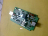
I am planning to tap a telephone line (to feed DTMF decoder as shown in the attachment) through an isolation transformer 600Ω/600Ω of 1:1 type. In our local market it is not readily avail. After a lot of search I have found one Dax 56K DX-56PU modem contains one Transformer .
Find the attachment T1 AASUPREME.
For using that Transformer I have to know the following details.
How can I know the following 4 specifications of the transformer,
Impedance matching (intended value is 600 ohms to 600 ohms)
Frequency response (intended value is 300-3400Hz for Plain Old Telephone System)
Turns ratio (intended value is 1:1)
Does it pass DC current through windings (otherwise I have to use separate capacitors at primary to block DC)
Complete Transformer specification-
aasupreme by
C US 0514
S022168A
I cannot get the specifications through internet.
Attachments
Last edited:
