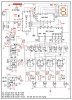
In figure both StD and B signal energize IC7 to produce AF beep signals. Does it is possible to combine these 3 control signals (one StD, two B) towards IC7 as each control signal occur at different times. If yes, how we can combine three inputs to a single transistor T4 base point.
One more doubt, if we fed back beep signal 'T' towards phone line directly without any couplers does it cause any loading problems when high volt ringing signal comes.