Continue to Site

Welcome to our site!

Electro Tech is an online community (with over 170,000 members) who enjoy talking about and building electronic circuits, projects and gadgets. To participate you need to register. Registration is free. Click here to register now.

  • Welcome to our site! Electro Tech is an online community (with over 170,000 members) who enjoy talking about and building electronic circuits, projects and gadgets. To participate you need to register. Registration is free. Click here to register now.

Zener reference voltage

Status
Not open for further replies.

jpanhalt

Well-Known Member
Most Helpful Member
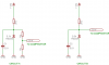
Below are two options I have considered to obtain a zener reference voltage less than 5.1 V for a comparator. A 1N5232 (5.1 V) zener is used in Circuit A, and the voltage divider will have a total resistance of around 20K. A 1N5224 (2.8 V) is used in Circuit B. The temperature coefficients are +0.04%/°C and -0.08%/°C, respectively. The comparator (LM393) is being used to maintain a fixed voltage across a large capacitor. A percent or two variation in that voltage will not matter.

My principal question is whether there is an established best practice to use one approach or the other? Also, any recommendations for the total divider resistance or other values would be appreciated.

Thanks. John
 

Attachments

  • ZENER REF.PNG
    ZENER REF.PNG
    13.9 KB · Views: 587
The 2.8V circuit will be more stable and be able to supply more current. Do you realise that the normal tolerance on those zeners is 20%. A voltage reference chip may be more suitable.

Mike.
 
Mike, Thanks for the prompt reply. This is actually for an adaptation of the spot welder circuit you gave a link to a few days ago. That circuit used an adjustable voltage regulator. I thought it would be at least as easy and provide more charging current to use a P-channel mosfet controlled by the comparator. I have a crude concept circuit working. I will post the completed circuit when available.

To answer your question, I don't think tolerance will be a big deal. The TIG and MIG welders I have used simply had a pot with arbitrary markings for "heat" or its equivalent. I will be doing the same. Reproducibility is more imortant than the actual voltage value.

Also, with the comparator, I can create a delay to have the relay disconnect occur a little before firing the SCR to be sure that part of the circuit is protected. John
 
jpanhalt said:
This is actually for an adaptation of the spot welder circuit you gave a link to a few days ago. That circuit used an adjustable voltage regulator. I thought it would be at least as easy and provide more charging current to use a P-channel mosfet controlled by the comparator. I have a crude concept circuit working. I will post the completed circuit when available.
John

I'll look forward to an account of how you get on.

Mike.
 
Status
Not open for further replies.

Latest threads

New Articles From Microcontroller Tips

Back
Top