Hi everyone,
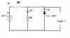
I studied how zener diodes work and tried to understand it. Partially, I learnt when its states change. However, in a circuit I can't find current and voltage of the components when a zener diode is included. Can anyone show me a way to solve these questions,a strategy or something?
I attached a circuit diagram to illustrate what I said. If you expailn by using this one or some other circuits, It will be much better.
Thank you.