Continue to Site

Welcome to our site!

Electro Tech is an online community (with over 170,000 members) who enjoy talking about and building electronic circuits, projects and gadgets. To participate you need to register. Registration is free. Click here to register now.

  • Welcome to our site! Electro Tech is an online community (with over 170,000 members) who enjoy talking about and building electronic circuits, projects and gadgets. To participate you need to register. Registration is free. Click here to register now.

Yet another PIC parallel port programmer

Status
Not open for further replies.

eblc1388

Active Member
Edited by eblc1388: I built it and it works, on 18F4455, 16F628A, 16F877, 12F675 but failed on a 16F88.
Edited 2nd time by eblc1388: User Someone Electro built a modified version of the schematic and using 13V as Vpp he can also program a 16F88, 16F876A and 18F4550.
Edited 3rd time by eblc1388: A programmer based on modified version of the schematic and using 9V+3V batteries built and tested

Hi everyone,

I found the following from the Microchip discussion forum. The original thread is here:

New LPT programmer

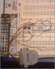
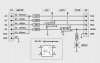
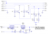
On first look the circuit is very interesting as it use very few components. I have modified the circuit a bit by adding two resistors. You may also use the 78L05 instead of the 7805 voltage regulator. In addition, I would also use two capacitors(not shown) for the voltage regulator as kind of good practice. If it does not work, you can remove them and try the original circuit.

I just wonder with the original circuit, PIC's MCLR pin voltage can never rise above the LED forward voltage drop of 2.0V, how it would work in this case. Not to mention the high current that would kill both the opto-couplers.

If you ever tried to build it, please post back to let us know of the result.
 

Attachments

  • brokebenji_.gif
    brokebenji_.gif
    24.7 KB · Views: 2,124
As you say, the original can't possibly work - there's probably not enough current available from the parallel port to blow the LED?, but it won't do the port any good!. As you also say, the second opto-coupler prevents MCLR from rising above 2V or so.

The two resistors you added might make it workable, and I would also add a couple of capacitors round the voltage regulator. Bear in mind, assuming it does work?, it will require a fairly accurate and stable supply voltage (as there's no MCLR regulation incorporated).
 
Nigel Goodwin said:
As you say, the original can't possibly work - there's probably not enough current available from the parallel port to blow the LED?,....

In the original circuit, the parallel port MCLR connection should have enough current to light up the top optocoupler which then switch the +12V or more to the LED of the bottom optocoupler without any current limiting. This would possibly destroy them both.
 
eblc1388 said:
Nigel Goodwin said:
As you say, the original can't possibly work - there's probably not enough current available from the parallel port to blow the LED?,....

In the original circuit, the parallel port MCLR connection should have enough current to light up the top optocoupler which then switch the +12V or more to the LED of the bottom optocoupler without any current limiting. This would possibly destroy them both.

Depends on the transfer rate of the optocoupler, but regardless - it won't work :lol:
 
I have good news to report.

The circuit works without doubt and I have photos to prove it. I have used two H11G1 optocouplers as I have them in my part box. I guess many other types can be used too as the timing is not at all critical.

Please note that I am using my modified circuit with the two resistors added and because my bench supply has +5V output, I get it there instead. This should make no difference between using one or a 78L05.

The voltages provided by my regulated supply are +12V and +5V exactly.

The operation was tested on a 18F4455 which I have previously programmed "1234" as the first word so I can use it to test my other programmers. The "3210" next to it is the actual data I programmed into the PIC using this setup. All went well.

To save you time in setting up the software WinPic800, I have included the setup page. Note the signal pins used is exactly what were said in the schematic. PC operating system is Win98SE.

All in all a simple and useful circuit for programming PICs. All credits to creator of BrokeBenji, whoever he is.

Have fun. If you get yours working, remember to post back for others to share your experience or circuit improvement.
 

Attachments

  • brokenbenji_2.gif
    brokenbenji_2.gif
    17.3 KB · Views: 1,761
  • brokenbenji_1.gif
    brokenbenji_1.gif
    20.5 KB · Views: 1,793
  • brokenbenji_3.jpg
    brokenbenji_3.jpg
    69.5 KB · Views: 1,795
Seeat programer.

When i saw the circuit i toght:"Yea its one of those chepo 16F84 programers"
And when i saw the pics : "WOW!!! This litle [Moderator Bleep] reay works!"

Too bad i dont have not one optocopler to try it out.(I toght that i wont need it so i didnt get "one",now i regret it)

If you use SMD parts this could make an realy tiny programer.
 
Question please? Why not feed the 'VDD' opto-isolator from the D2 pin on the parallel port? Isn't this pin normally used for VDD switching by many Tait style programmers anyway? It seems this would allow the smarter programming software to apply the correct VPP-first or VDD-first algorithm as necessary to put the target device into high voltage program/verify mode...

Regards, Mike
 

Attachments

  • programmer_optocoupler__2.jpg
    programmer_optocoupler__2.jpg
    37.8 KB · Views: 1,636
I would add some pull down to the Vpp Becose a PIC is CMOS and that litle voltage may jusr leak trough that optocopler.10k sould do.
 
Mike said:
Question please? Why not feed the 'VDD' opto-isolator from the D2 pin on the parallel port? Isn't this pin normally used for VDD switching by many Tait style programmers anyway? It seems this would allow the smarter programming software to apply the correct VPP-first or VDD-first algorithm as necessary to put the target device into high voltage program/verify mode...

Regards, Mike

Yes you can separate them but I believe that the Vdd first device would still work even in Vpp first mode. The converse is definitely not true. I have no proof and have not tried any.

Can you just resist the temptation of building such simple programming device and evaluate its result? I couldn't.

Someone Electro said:
I would add some pull down to the Vpp Becose a PIC is CMOS and that litle voltage may jusr leak trough that optocopler.10k sould do.

Do you think the LED after the 2K2 has leakage current to ground?
 
eblc1388 said:
Someone Electro said:
I would add some pull down to the Vpp Becose a PIC is CMOS and that litle voltage may jusr leak trough that optocopler.10k sould do.

Do you think the LED after the 2K2 has leakage current to ground?

Yes, it should act like a pull-down... I went back to my drawing and added a 'Busy' LED and 1K2 resistor to provide the same function...

That WinPIC800 program looks pretty decent... I'll have to order some optocouplers (grin)...

Regards, Mike
 
I made the programer whith a litle mod to it.First i tock one data pin to the second opto and added status LEDs on the Vpp and Vdd. Also an ptity power on LED and and regulated 13V rail becuse i have an 16V wall wart that outputs near 20V open cirucit (Ok you can call me LED crazy)

It programed an 16F88 fine.Im yet to test it on some other PICs.If this goes well im gona solder it all togeter.And i hope it goes well.
 
Someone Electro said:
It programed an 16F88 fine.Im yet to test it on some other PICs.If this goes well im gona solder it all togeter.And i hope it goes well.

There's no reason it shouldn't, it's not really any different to most other parallel port programmers, in that it uses open-collector buffers (just in this case they happen to be opto-couplers).
 
I know those work well too.This one is nice and small but works.

I also tested it on the 12F675 and the 16F876A.Works whithout a hitch.
 
Alo tested on the big 40pin 18F4550 and works works wroks! :p

Ok now im out of difrent PICs

Works on all PICs i own.

So the list for my programer is:
-PIC16F88
-PIC16F876A
-PIC12F675
-PIC18F4550

Myne is prety close to mikes schematic.

Let the soldering begin!
 
Now you have made some modification and it also worked for 16F88. Congratulations.

I think you should draw up and post the exact circuit so other users can repeat what you did. You also need to include other changes(if any) like software settings for this little project to be useful.

I have modified the top of thread to inform others that you have made one that programs the 16F88.
 
Ok here is my opto PIC programer.

It uses the LPTs curent limiting so no resistors on the optos.

Settings are almost the same

Tested and works on:
PIC16F88
PIC16F876A
PIC12F675
PIC18F4550
 

Attachments

  • opto_pic_programer.png
    opto_pic_programer.png
    15.5 KB · Views: 962
  • opto_prog_settings.png
    opto_prog_settings.png
    23.9 KB · Views: 1,037
Status
Not open for further replies.

Latest threads

New Articles From Microcontroller Tips

Back
Top