Continue to Site

Welcome to our site!

Electro Tech is an online community (with over 170,000 members) who enjoy talking about and building electronic circuits, projects and gadgets. To participate you need to register. Registration is free. Click here to register now.

  • Welcome to our site! Electro Tech is an online community (with over 170,000 members) who enjoy talking about and building electronic circuits, projects and gadgets. To participate you need to register. Registration is free. Click here to register now.

Yet another Night Rider LED project

Status
Not open for further replies.

Mike - K8LH

Well-Known Member
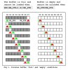
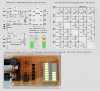
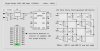
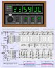
After completing a 12F683 based Serial Bar/Dot LED controller project last year (below) I realized that a stripped down version using a Charlieplexed type LED matrix could put a whole new slant on a minimal hardware version of that simple "Night Rider" LED project we all built long ago (grin)...

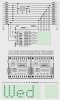
So please enjoy project "Night Rider 2006 (12F683)"...

Regards, Mike
 

Attachments

  • led_bar-dot_prototype.jpg
    led_bar-dot_prototype.jpg
    103.6 KB · Views: 14,193
  • night_rider_12f683.zip
    2.3 KB · Views: 665
  • night_rider_2006_v1.jpg
    night_rider_2006_v1.jpg
    47 KB · Views: 8,013
Hi Mike,

In your "K8LH Serial Bar/Dot LED Controller" circuit, is there a reason for using NPN transistors Q1~Q5 instead of PNP transistors to drive the LEDs?
 
eblc1388 said:
Hi Mike,

In your "K8LH Serial Bar/Dot LED Controller" circuit, is there a reason for using NPN transistors Q1~Q5 instead of PNP transistors to drive the LEDs?

Yes, the NPN transistors are turned on with an "active high" signal required for Charlieplexing columns with common anodes... If you'd like to work through a truth table then consider that only one of the five pins will be an output '1' (high) at any given time to drive a column and the other four 'row' pins will either be an output '0' to light an LED or a hi-Z input to leave the LED unlit...

Regards, Mike
 
Mike said:
Yes, the NPN transistors are turned on with an "active high" signal required for Charlieplexing columns with common anodes...

The reason I asked is a NPN can never be turned fully ON in this configuration and you might not be able to pulse a lot of current into the column.

A PNP transistor, on the other hand, can be easily turned fully ON(saturate) with a LOW on the PIC pin. That's why some 90% of multiplex display scheme use PNP transistors for CA column drive.

I have also noticed that you use PNP transistors to ground for CC LEDs on your designs and it too suffer the same problem as NPN in this case.
 
Someone Electro said:
Where are the curent limting resistors?

Current limiting resistors are not required for typical 20-ma LEDs in these circuits... The I/O pin limits current to 20-ma (source) or 25-ma (sink) which is actually less than ideal for these duty cycles...

If you were to use low current LEDs (3 or 4-ma) then current limiting resistors might be required...

Regards, Mike
 
eblc1388 said:
Mike said:
Yes, the NPN transistors are turned on with an "active high" signal required for Charlieplexing columns with common anodes...

The reason I asked is a NPN can never be turned fully ON in this configuration and you might not be able to pulse a lot of current into the column.

A PNP transistor, on the other hand, can be easily turned fully ON(saturate) with a LOW on the PIC pin. That's why some 90% of multiplex display scheme use PNP transistors for CA column drive.

I have also noticed that you use PNP transistors to ground for CC LEDs on your designs and it too suffer the same problem as NPN in this case.

I didn't know that... But if I were to change the drivers do you think I'd see a difference since the LEDs are current limited (under driven) to the I/O pin 20-ma spec'?

Regards, Mike
 
Mike said:
I didn't know that... But if I were to change the drivers do you think I'd see a difference since the LEDs are current limited (under driven) to the I/O pin 20-ma spec'?

You'll need base bias resistor to limit the base current to the transistors.

The saturation of the PNP transistor would enable the max. I/O pin current to flow into your LED so it should be brighter than if the NPN transistors are used.( I think previously there could be as high as a one volt drop between the collector-emitter in your NPN transistor)
 
I'm already getting the max I/O current from each pin so I'm not certain that changing the transistor type would improve brightness... The I/O pin current spec' seems to be a limitation for the Charlieplexing scheme... The 20-ma or 25-ma current limit just doesn't provide 'best' brightness...

Regards, Mike
 
Mike said:
I'm already getting the max I/O current from each pin so I'm not certain that changing the transistor type would improve brightness... The I/O pin current spec' seems to be a limitation for the Charlieplexing scheme... The 20-ma or 25-ma current limit just doesn't provide 'best' brightness...

Regards, Mike

Yes, you've got a very good point here. The PIC pin I/O MOSFET behave like a constant current source to ground so you won't get much higher current thus higher LED brightest using the PNP transistors setup instead.

Someone did ask in the Microchip forum whether he can pulse the current with a higher value but apparantly the current is limited internally because of the physical cell structure of the MOSFET.
 
On a somewhat related note -- yesterday I designed a more "traditional" multiplexed circuit for my Clock project (below) and this morning I wired up the 16F88, MIC5841, and the COL1/COL2 LEDs on a solderless breadboard and had full PWM fading test code debugged and running in a couple hours...

Absolutely incredible brightness on the green displays that I'm using and I suspect probably more than enough drive for those exotic new 1.0" white and 4.0" blue displays I've seen... And not only can I change brightness level on the entire display to match room lighting conditions, I can also change the brightness level per column or digit for some interesting special effects... I originally just wanted to smoothly fade the display to black and back momentarily when switching modes (CLK, ALM, TMR, CAL) but now I can't wait to test code that would fade changing clock digits for a pseudo 'morph' effect... I'm really 'geeked' (grin)...

Regards, Mike
 

Attachments

  • concept_-_clock_8x8.jpg
    concept_-_clock_8x8.jpg
    141.7 KB · Views: 867
  • concept_-_clock__2.jpg
    concept_-_clock__2.jpg
    181.6 KB · Views: 650
Hi Mike,I don't mean to carry it off the topic,but I wonder what software you were using as shown in your picture attachment. :)
 
Hi Alex,

The drawings are Excel 2000 spreadsheets...

Take care... Regards, Mike
 

Attachments

  • circular_buffer_diagram.jpg
    circular_buffer_diagram.jpg
    74.7 KB · Views: 542
Mike said:
Hi Alex,

The drawings are Excel 2000 spreadsheets...

Take care... Regards, Mike

Very impressive! - can you save them as a different format?, using JPG is making the file excessively large and of reduced quality - if you can save it as GIF or PNG (but NOT by converting it from a JPG!) the quality will be perfect, and the file size much reduced.
 
Mike said:
Hi Alex,

The drawings are Excel 2000 spreadsheets...

Take care... Regards, Mike
Thanks Mike,I thought it was an advanced simulation software which I had never seen before.I have Proteus on my school PC,and it simulats analogue circuits as well as microcontrollers.You construct the scheme with the uC you want,and import its code.Then the software runs the code inside the virtual uC.The effect looks so real!

BTW I prefer editing my graphic scripts with MSpaint,save it as gif or jpg file.Only when I don't need high quality :)
 
Status
Not open for further replies.

New Articles From Microcontroller Tips

Back
Top