Continue to Site

Welcome to our site!

Electro Tech is an online community (with over 170,000 members) who enjoy talking about and building electronic circuits, projects and gadgets. To participate you need to register. Registration is free. Click here to register now.

  • Welcome to our site! Electro Tech is an online community (with over 170,000 members) who enjoy talking about and building electronic circuits, projects and gadgets. To participate you need to register. Registration is free. Click here to register now.

Yamaha RX-496 Noise On Right Channel

Status
Not open for further replies.
Hey all,

I've got a Yamaha RX-496 receiver that's acting funny.

Here's a video of my scope connected to the Right "A" speaker. Notice the noise that starts immediately after powering on:

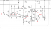
This noise occurs with the input to the amp's "power board" disconnected (R + L signals). I clipped the R & L lines coming into the "power board" (p.38 in PDF) to attempt to isolate the problem - since it is still happening I assume the problem is on the "power board"

The problem does not occur on the L channel.

Probing the R input on the "power board" (the wires I clipped) I see a similar waveform (but much lower amplitude). I also see a similar waveform on the emitters of the power transistors. Amp power rails appear normal (53v/-53v).

I've attached the repair manual including schematic. Any ideas would be appreciated!
 

Attachments

  • yamaha_rx-496_396.pdf
    7.2 MB · Views: 1,342
Collector voltage on both Q101/Q102 is around -53v

Why C103? That seems like its part of the left channel.
Replaced C102 and C110 as I happened to have replacements handy, but no change.

I'm debating rebuilding the input section of the amp (everything to the left of Q110/Q112) since I have to place a DigiKey order for some other things. Would this be advisable?
 
I had a hard time discerning what part went with what channel, so I picked both of them. Sorry if I confused you.

I have seen a lot of issues with electrolytic caps used in the coupling circuits of the audio path. These 1 uf to about 4.7 uf should not be electrolytics. Metalized polyester would be a better choice in the audio path.

The voltage readings I was after was for E/B and C for Q101/102

I'm having a hard time believing that this may be power supply noise, but I have not seen anything like that before. I didn;t look close enoghh as to whether o not the amp supported multirail supplies.

I'd have to print the schematics and look a bit closer.

If this AMP has a tape monitor loop and or main/ pre out, Is suggest reversing the L and R channels there, to isolate the amplifier at fault or just disconnecting. The tape monitor loop usually has the same effect.

In rebuilding, I'd primarily change the coupling caps to metalized polyester and I would put ZNR's across each of the amplifier filter caps if they are not there. I'd think I'd wait, until the issues is fixed, though.

The general rule for troubleshooting are essentially:
1) Inspect and/verify customer's complaint. You could find roaches or loose screws or even sandwiches in a VCR. Brand new auction site stuff needs an inspection before power up. Your past that stage.

2) Check ripple and power rails everywhere. They are a no-brainers. I didn't look close enough to see if the L and R channels used the same power rail. Consumer stuff usually doesn't An amp I built does.

3) Isolation
True, you have it down to the right channel, but you can cross the left and right channels at the tape monitor and/or pre/main inputs/outputs.
You have at your disposal, injection and bisecting the signal path and you can even remove the main.pre jumpers and see what happens at the output.

You have a schematic and you can use comparison.

I might even consider thermal comparisons between left and right. Finger, thermometer or an IR thermometer. If something is oscillating, it's probably heating up more.

I didn't catch the frequency or the magnitude of the noise at the speaker terminals. The DC voltage at the speaker would be useful too.
 
Sorry for the delay in responding.

It's surprisingly easy to differentiate which part is on which channel - even-numbered parts are on the R channel, odd-numbered parts are on the L channel :)

Amp is physically clean inside - no bugs/loose parts. Solder joints look fine, no corrosion on the board. Power supply rails are stable. Same rails feed both channels, and they are 52.6/-52.9v respectively.

Regarding the tape monitor loop, I've disconnected the input to the power board from the input board, so there is no signal being fed into the amp. I would expect no output, but I would be wrong!

I have attached the right schematic with some voltages annotated. Right off the bat Q102 has a high base voltage (0.6v) that seems to contradict the schematic (0v). Also, the junction of the two emitters is much lower (0.02v) than the schematic indicates (0.6v). The junction of the collector of Q106 and emitter of Q108 ("-4 to 4v") seems to be oscillating, or generating noise.

There are spikes of +/-20v DC on the speaker outputs. The amp has started shutting itself off randomly - I suspect the protection circuitry is picking up on something being awry.
 

Attachments

  • 1_Page_38 - Copy.png
    1_Page_38 - Copy.png
    134.8 KB · Views: 403
In circuit with the power off, use the diode test on you meter and check the B-E voltages with the diode test on your meter. You should get around 0.6 V in one direction,

If you don't, stop and don't go any further.

With no speaker connected.

Measure between the base of q110 and the base of q112 and see if it's steady between 1 and 2 Volts.

If it isn't, I think you can get away with lifting a leg of both R134 and r136, then measure between the base of q110 and the base of q112 again.
 
Status
Not open for further replies.

Latest threads

New Articles From Microcontroller Tips

Back
Top