Strablan
New Member
Hi All
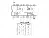
Im trying to get the above chip to work but without any luck, probably something simple that Im missing. Looking at the data sheet for the chip I have all the pins sorted, 7 to ground, 5 volts to 14 and using pins 1 & 2 for inputs. However I can't get any change out of pin 3 (output) no matter what I do with pins 1 & 2. From what I understand if either of the inputs goes high, pin 3 will go high otherwise remain low. What voltage does either of the input pins require to be classed as high ? Is there a straight forward way to test the chip.
Many thanks for any help
:?