Vizier87
Active Member
hi guys,
Back to business for me after learning heaps of optical circuits (but my programming still stinks )
)
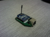
I connected an Xbee to both my uCs, 877A as a transmitter and 4455 as a receiver. I powered my Xbees up using a 3.3V regulator, and the rest is pretty much direct I suppose.
I checked the output of the transmitter using an O-Scope and got a nice square wave, and the same square wave at the receiver end. So i suppose the program's the one making the problem.
It's all simple: The received data will be displayed at PORTD. So far I received nothing.
Here's the transmitter (PIC16f877A):
The receiver is a PIC18F4455:
Appreciate the time spent on this. Thanks.
Vizier87.
Back to business for me after learning heaps of optical circuits (but my programming still stinks
)I connected an Xbee to both my uCs, 877A as a transmitter and 4455 as a receiver. I powered my Xbees up using a 3.3V regulator, and the rest is pretty much direct I suppose.
I checked the output of the transmitter using an O-Scope and got a nice square wave, and the same square wave at the receiver end. So i suppose the program's the one making the problem.
It's all simple: The received data will be displayed at PORTD. So far I received nothing.
Here's the transmitter (PIC16f877A):
C:
void main() {

 adcon1=0b00000111;  //pcfg settings: all digital I/O
 cmcon= 0b00000111;  //comparators off
 cvrcon=0;           //voltage comparators off
 txsta=0b00000100;   //8-bit, Async mode, Hi-Speed,
 intcon=0b11000000;  //enable all peripheral interrupts
 spbrg=129;           //9.6 kBps

 trise=0x07;         //porte=input, pspmode_bit=0;
 trisa=0b100000;     //ra5=input
 trisd=0xff;         //rd4=input, rest output
 trisb=0;            //portb=output
 trisc=0b10111111;   //input for keypads and RX=input/TX=0utput

 spen_bit=1;        // serial port enable
 portb=0;
 porta=0;


   while (1){

        txreg=0xAA;
        txen_bit=1;

   }
}
The receiver is a PIC18F4455:
C:
void main() {

trisd=0;
latd=0;

spen_bit=1; //enable rx-tx
rx9_bit=0;  //8-bit
cren_bit=1;//enable receiver


sync_bit=0;        //asynchronous mode selected
brgh_bit=1;        //hi-speed
brg16_bit=0;       //16-bit not selected

trisc=0b10000000; // rc7=input
intcon=0b11000000; //enable all interrupts

spbrg=129;         //9.6 kbps

while (1){

      rcreg=portd;

  }
}
Appreciate the time spent on this. Thanks.
Vizier87.