Continue to Site

Welcome to our site!

Electro Tech is an online community (with over 170,000 members) who enjoy talking about and building electronic circuits, projects and gadgets. To participate you need to register. Registration is free. Click here to register now.

  • Welcome to our site! Electro Tech is an online community (with over 170,000 members) who enjoy talking about and building electronic circuits, projects and gadgets. To participate you need to register. Registration is free. Click here to register now.

Wrong transistor or wrong positioning

Status
Not open for further replies.

Icadj

New Member
Hi there all

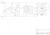
As you can see by the diagram I have used BC547 from a 4017 to trigger a relay. (idea modified from ericgibbs drawing)

Everything works fine but what is happening is the transistor/relay are staying "on" apart from when its being pulsed by the 4017. info confirmed by multi-meter at 4017 & transistor/relay

What I want, is the transistor/relay to be on "ONLY" when the 4017 pulses.

Can anyone please tell me
1. should the transistor be moved to switch a positive voltage or
2. use a different transistor to switch a negative voltage or
3. a different transistor and moved to switch a positive voltage

many thanks
steve
 

Attachments

  • 555 short on long off+4017+TRANS+RELAY V2.JPG
    555 short on long off+4017+TRANS+RELAY V2.JPG
    259.1 KB · Views: 180
  • AAesp01.gif
    AAesp01.gif
    39.6 KB · Views: 151
hi,
If the relay is working in the opposite sense than you require ie: when the output pin of the 4017 is high, its possible that the BC547 is incorrectly connected.[reversed???]

Also I would add a 47K from the BC547's Base pin to 0V.
 
Last edited:
Why are you applying a signal (reset b) to pin 11 of the 4017? Pin 11 is an output.
 
Why are you applying a signal (reset b) to pin 11 of the 4017? Pin 11 is an output.

Hi Alec, I think he just has an arrow backwards. Pin 11 is used for a reset.

Ron
 
hi there everyone thanks 4 the reply

the "triangle" on pin 11 is mean to represent a soldiering pin

Eric ,, i am fairly certain that the transistors r the right way round even if I had to program* the BC547 into the program *shape & pinouts* (see upload)

The resistors & diodes show a band on then ,, I know this is the wrong way round its what the program (veecad) "does" found out the hard way when nothing worked to begin with, thats why they have red bands now.

Can u tell me why the use of a 47K pull down resistor at the base of the BC547 is it that help with the triggering

cheers
Steve
 

Attachments

  • PCB 555 slow trigger.jpg
    PCB 555 slow trigger.jpg
    274.9 KB · Views: 141
hi steve,
Can we just recap,,,
When are the LED's lit and when not lit.?

Is the 4017 stepping thru the 0 to 9 outputs.?
 
Last edited:
hi eric
The LED's r working fine thanks to you and to previous postings

The problem is the transistor/relay (#1 post this posting) they seem to be reversed. Also reduced use of 4017 ,, to one 4017 using the following pinouts

pin 3 used - trigger a (relay a)
pin 2 NOT used
pin 4 used - trigger a (relay a)
pin 7 NOT used
pin 10 used - trigger b (relay b)
pin 1 reset

hope that make sense

I have been using tinycad from the drawings and veecad for the stripboard layout, dont think I can upload the files as not covered by file extensisons uploader.

thanks
steve
 
hi,
If the transistors are connected to the transistor as shown and the relay way the relay as drawn on post #1, then the relay should only be energised while the 4017 driving pin is high.

What voltages do you measure on the 4017 diode driving pin and the collector of the transistor when the relay is energised.?
 
hi
voltages where roughly 10 to 11.5 at the collector coz I thought this should only be on for a blink and it was not
and oh heck that was ? ? ? ? ? pulsed

Sorry eric I cant answer that properly , can we please carry on after xmas or new year when I can get the meter out and do it properly and not guess as I have had to pack up coz family are due soon and I thought they was coming 2moro so I'm not gonna get another chance until after boxing day

Should I continue this post or start fresh ?

Many many thanks to you, have a good holiday
steve
 
hi steve.
We can resume after the New Year... have a good one.

Eric
 
Sorry to bring this up now, right after you asked for a break, but how fast are you running your clock to the 4017? I've had the problem of the relay "sticking" at higher frequencies. I think it doesn't have time for the magnetic field inside to dissipate and allow the contact to spring back before another pulse is received. Is it possible that you're running it too quickly?

Have a very merry Christmas and a happy new year :)

Best wishes,
Der Strom
 
Status
Not open for further replies.

Latest threads

New Articles From Microcontroller Tips

Back
Top