Continue to Site

Welcome to our site!

Electro Tech is an online community (with over 170,000 members) who enjoy talking about and building electronic circuits, projects and gadgets. To participate you need to register. Registration is free. Click here to register now.

  • Welcome to our site! Electro Tech is an online community (with over 170,000 members) who enjoy talking about and building electronic circuits, projects and gadgets. To participate you need to register. Registration is free. Click here to register now.

Writing 2 Graphics Lcd Using Pic

Status
Not open for further replies.

cyprio7

New Member
hey guys. iv been trying to write to an lcd i purchased using a PIC16F628-4mhz but iv been having no luck.

iv written the program to just set up a few simple things on the lcd, and to display a blinking cursor, thats all, but when i try to load the program onto the pic it says that the program is larger than the memory on the pic.

if this is true then i think i am in big trouble because i am trying to create a list of about 50 songs whose names will be displayed on the LCD and the user can scroll up and down to see the list.

at the moment i cant even get my program (which all it does is theoretically make the lcd display a blinking cursor) to load onto the pic.

i am using MGLS12864T graphics lcd which has a built in T6963C Toshiba lcd controller.

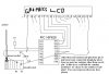
i will submit my program which hopefully will help... below is what pic pins i am using to send to which lcd pins so u know what the program is doing...


PIC LCD

ra1 >> /RD
ra0 >> /WR
ra7 >> /CE
ra6 >> C/D

rb0-rb7 >> DB0-DB7 (data lines)


any help would be greatly appreciated

thanks
 

Attachments

  • write to lcd.asm
    3.3 KB · Views: 342
You should have no problem with that file. It uses less than 100 words out of 2048 allowed. To store 50 names would require the average name length to be somewhere around 32 characters. If you need to store more then just switch to a chip with more memory - 16F648 or 16F88.

Mike.
 
thanks for your reply mike. iv written the program using MPLAB, i built the project to produce a hex file which is 542bytes big. i send this file to the PIC using PICmicro Parellal Programmer software and a programmer that my friend built for me. i tried loading a couple of nigels programs on just to test if it works and its fine, but when i load my one it says "record type is not '00' or '01' - make sure INHX8M format is selected"...... i press ok then it says "ERROR: Program is larger than [16F628] program memory space". do you think you might know what the problem is? do you think it could be the programmer/programmer software and not the hex file im trying to send?

thanks
 
Hi there, I was trying to ask you a question or two about this yesterday, but then they moved the forum and I lost the post I'd written. Twice in fact! :rolleyes:

However, you've since answered both the questions there before I even got to ask, so heh :D Anyhow: I dunno anything about MPLab, but I use GPASM (which is an MPASM clone for Linux), and that produces INHX32 hex files by default. Perhaps MPASM/MPLab does so too? GPASM can also produce other formats too though, including INHX8M, so I had a go at assembling your source file just now to that format, partly to see if I could figure out how they differ or which parts were the "record type" the programmer's complaining about (I assume the first 2 digits per line).

I couldn't quite figure that out, but here's what I got out all the same, in case it works better for you? :) If it does, you probably need to poke about in MPLAB to find where the settings are to get the INHX8M output. It'd seem odd for it to have previously made files that your programmer accepted ok though. Oh yeah, I had to upload this as a .txt file so the forum would accept it :rolleyes: so you'll probably have to rename it to .hex :)
View attachment lcdwrite_inhx8m.txt
 
To change the output format in MPLAB goto Project/build options/project and select the MPASM tab. In the dropdown box select "output" and you can change the hex file format.

The record type in a hex file is the 4th byte on the line,
:100000003A28831203136430A000A00B05280800CF
The above is record length, address, record type, data, checksum.

Mike.
 
i swear im so dumb. i just couldnt take it anymore and i was just staring at MPLAB in anger and then wen i was daydreaming i saw a "0" where it should have been a "1". i was keeping the reset button of the lcd pressed down all the time!!!!!! i got so excited an i corrected it and i am able to partically initialised the lcd and display some stuff on it, i say partially because here is the problem...


i had a a fair bit of code and the lcd wasnt working how i wanted it to so i reduced the code significantly, and i am trying to do a basic initialisation of lcd, and display two letters, "T" on the first line, and "u" on the second line... now here are the problems..


when i write code to display "T" and "U" on the same line one after another, it works perfectly, however when i modify the code so that "u" can appear on the second line it doesnt work.

the memory location on the lcd for text ranges from 00 to something greater than FF but thats irrelivant. im using a 128x64 lcd, with siez 6x8 font. 128/6 = 21.3 which means i can display a max of 21 characters on one line.

i set the text area of the lcd to 21, which means, there are 21 columns, the first column ranges from 0 to 20, and the second column starts on 21 (these numbers are memory locations for text on the lcd).

i configure the lcd to have 21 columns, and i set the address pointer to "00" and write the "T" on the first column top left corner, then i set the text pointer to "21" (so that its on beggining of second line), and i write and program pic.


now get this.. the pic programmer has a built in breadboard, and i am supplying two of those breadboard pins with Vdd and Vss, with two wires, these are plugged into the breadboard from the lcd(and pic)... and the programmer has a powersupply socket where i connect a proper powersupply. when i take out the Vcc wire from the bread board, and touch it again, and take out, and touch it again, the display on the lcd changes to something else every time!!! but if i leave that wire in, and i disconnect the programmers proper powersocket and put it on, then the lcd always displays(most of the time) the last thing that was on the screen.


i am using those very bendy wires which r made of many strands of wire because the single wire ones snap easily.

this made me think there could be a problem with the wire supplying the 5v but then i though nah cant be.

i thought mayb my algorithms for writing to lcd arent correct but they must be other wise it wont be displaying what i told it to display, im guessing communication with LCD is ok. i set address pointer to 21 and write, but instead of going to second line, it just flows off the screen, so i change the text home address (upper left corner of screen) to 21 and low and behold the "u" is in the top left of the screen. i just dont get why. i have connected all pins with just a piece of wire with no resistors other than ra5/mclear.

i took out my multimeter and put it in diode mode so that i can check if there are any shorts.. when there is a connection the multimeter shows a few random numbers initially, beeps and then displays "000", when there is no connection it shows 1, when i was testing the adjacent tracks of the lcd and pic, most of them read "1" and there was no beep, but on a few tracks the numbers went all random and crazy on the screen BUT there was no beep? does this mean something? iv checked the software so many times, so now im building it again to check hardware. could someone please tell me how to do in software a proper POWER ON RESET and configuration for pic16f628 because i am unsure mayb i am doing this wrong.


i have attatched the "simple" code that im using to do what im describing above. i am using toshiba 6963C controller whos datasheet can b found easily on net, my posts above show what pins of the pic iv connected to which pins of the lcd.

iv been going in circles for weeks and im going crazy. please help me.

thank you
 

Attachments

  • test prog.ASM
    5.4 KB · Views: 289
  • graphiclcdpicture.JPG
    graphiclcdpicture.JPG
    50.5 KB · Views: 361
oh and i managed to fix the program memory space on the pic thing thanks guys.
 
can someone at least tell me if im connected the pic and lcd together correctly please. can i connect rb0 of pic to the data line db0 of the lcd directly with a single wire? or do i have to use a resistor in series with that? do i have to put a resistor in series between the 5V power supply and Vdd pins on the pic and lcd? thanks
 
Status
Not open for further replies.

Latest threads

Back
Top