Continue to Site

Welcome to our site!

Electro Tech is an online community (with over 170,000 members) who enjoy talking about and building electronic circuits, projects and gadgets. To participate you need to register. Registration is free. Click here to register now.

  • Welcome to our site! Electro Tech is an online community (with over 170,000 members) who enjoy talking about and building electronic circuits, projects and gadgets. To participate you need to register. Registration is free. Click here to register now.

Would anyone mind simulating this simple circuit for me?

Status
Not open for further replies.
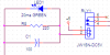
I don't have a circuit simulator program and my analog design skills are lax. If anyone would mind running this very simple circuit through a simulator I'm looking for values for R & C so that 20ma flows through the LED when the relay is energised. The circuit is pulled to ground via a ULN2803 darlington array.

The Relay datasheet can be found here.
**broken link removed**

Thanks in advance.
 

Attachments

  • relaymath.png
    relaymath.png
    3.8 KB · Views: 699
I think your circuit is incorrect. You want the resistor to be in series with the LED. You dont need the capacitor. It doesnt even need to be simulated.

Assume the UN2003 saturates at ~ 100mV when "ON", give the relay contact about 50milli-Ohms of resistance.. both of these are unimportant to calculating the LED current. LED might have about a 1.5V drop at 20mA (check datasheet - its based on color) so resistor ~ 175.. so 200 Ohms resistor is fine..


If you are worried about relay contact bounce, I doubt you'll see that in the LED. If you insist, at least return the capacitor to ground and not the 2003 driver.

Fix your circuit though.
 
I think the point of the capacitor is to allow enough of a current kick to actually switch the relay, and then when it charges up after a short time the current is reduced to just enough to keep it on. thus the whole energy-saving idea.
 
Do it like this:
 

Attachments

  • relaymath_188.png
    relaymath_188.png
    3.8 KB · Views: 542
Actually the circuit is from a small article in Elektor magazine. Although the LED will show when the relay is energized it also acts as part of the circuit. It's a power saving circuit, the cap should act like a short till it takes a charge then the LED and resistor limit the current to 20ma to the relay.

I'll find the article and post it. I do recall he mentioned GREEN LED, 20ma, 10 to 1K ohms and 100 to 400 uf for the Cap @ 6.3v

Claims to reduce the power draw to approx 50% or so without using a PWM.
 
JW1SN family has 5VDC member as shown in his circuit.
i don't think this circuit will work on only 5V because of considerable
voltage drop on LED and relay is probaly not going to hold reliably.
Circuit is not worth simulating because relay is mechanical device
and factors like spring force, friction and holding current are not known.
if you insist on energy saving don't use relay and if you must, you will
also have to do some experimenting to get the values right.
diferent color LEDs have different voltage drop and if i recall correctly
lowest Vf is for red LEDs. this should work ok even with 5V but LED might need to go or it could be added in parallel branch as shown by audioguru.
to save power, series resistor for LED would have to be increased to
reduce LED current to lowest acceptable level (it affects brightness).

edit:

I'll take that back. Circuit and shown values do make sense but we won't know
for sure without actual test. I checked datasheet and it does show pickup and
drop out voltages (at least the max values). Coil current is some 100mA, and
this is why resistor was in parallel with LED. With coil resistance of 47 Ohm and
that current of 100mA, voltage drop would be 4.7V. LED will require some
1.7-2.2V to operate and can take 20mA (that's about 100 ohm).
With 120 Ohm in parallel and coil in series, whole circuit would draw some
50mA which could be enough to hold relay. Capacitor size is not critical
(doesn't affect current saving or circuit consumption) and can be increased
if required until relay can pickup reliably.
 
panic mode said:
JW1SN family has 5VDC member as shown in his
if you insist on energy saving don't use relay and if you must, you will

yea relays are so 19th century ;)

@William

an article I read not too long ago on EDN showed how to take a common pair of N chan mosfets and use them to switch AC currents... i'll see if I can dig that up
 
Don't worry about the 5V relay not working. It is guaranteed to pull-in at 3.5V and drop-out at only 0.5V.

In your circuit, with the 2.2V LED in series with the low resistance (5V, 47 ohms) relay coil then the LED and 220 ohm resistor's current is 60mA. The 220 ohm resistor will conduct 10mA leaving 50mA through the LED, but its absolute max current is only 30mA.

If your green LED's forward voltage is exactly 2.2V then the resistor could be 56 ohms and the LED's current will be a safe 21mA.
You could use a 3.3V blue LED and increase the resistor's value to 200 ohms to reduce the total current even more to 36mA.
 

Attachments

  • relaymath_748.png
    relaymath_748.png
    6.8 KB · Views: 463
Blue LEDs are fairly inexpensive today.
In the first moment after the circuit switches on, the capacitor has 0V across it so the full 5V is across the relay's coil, activating it. After a short time when the capacitor is charged then it doesn't draw any current and the resistor in series with the relay coil reduces its current.
 
This relay circuit is a neat idea.
A number of years ago I did something similar, but the purpose was completly different. The reason was to dissipate less power in the relay coil than the on resistance of a Power Mosfet. A number of years ago the Rds of the power mosfet's was no where it is today. Even today the power dissipated by the poser mosfet is = Id squared by the Rds. Relays have contact resistance and this on new relays is very low. So if one is to calculate the power dissipated in relay contact resistance and add the power consumed by the energized coil the two can exceed the power dissipated in turned on power mosfet. If once the relay is energized the coil voltage is reduced to less than than 1/2 nominal coil voltage the power consummed by the coil is 1/4 that at normal coil voltage.
In simple terms a number of years ago a power relay with half the coil voltage dissipated less power than a power mosfet. To confirm this I actually measured the contact resistance of a DC relay at full coil voltage and then at 1/2 coil voltage. One would assume the with less coil voltage the pull from the magnetism on the contacts would be somewhat less. On a new relay I could not measure any appreciable difference. I was measuring contact resistance in the range of .002 ohms
 
if you don't have LEDs with higher Vf, you can add regular diode in series with it (1N4148, 1N914,...)
 
Hi Bill,
I'm in Mississauga, fairly close to Toronto.
I can see the tall buildings and CN Tower in downtown Toronto from my bedroom windows. :lol:
 
Status
Not open for further replies.

Latest threads

Back
Top