Continue to Site

Welcome to our site!

Electro Tech is an online community (with over 170,000 members) who enjoy talking about and building electronic circuits, projects and gadgets. To participate you need to register. Registration is free. Click here to register now.

  • Welcome to our site! Electro Tech is an online community (with over 170,000 members) who enjoy talking about and building electronic circuits, projects and gadgets. To participate you need to register. Registration is free. Click here to register now.

working with a phototransistor

Status
Not open for further replies.
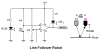
Hi, i bought this photo transistor and connected it as showen in this schematic and it doesnt really work , i used an ultrabright led to shine light on a surface (black and white ) and measure the analog value , no voltage swings between white and black just few mV between both colors.

I tried 1k , 10k , 100k resistors and doesnt swing and 180K resistor it swings but with +- 2V between white and black ...

i dont know how to choose the value of this resistor ?

https://www.electro-tech-online.com/custompdfs/2007/12/PT204_6C.pdf

here's the datasheet
 

Attachments

  • bs.JPG
    bs.JPG
    46.5 KB · Views: 391
Last edited:
I think that is a IR (infra red) photo transistor. I can't see the data sheet at the moment.

Mike.
 
Have you tried using a regular light bulb (with more IR than a visible LED) and a black/white material that you re sure is not transparent to IR?
 
Its response peaks at infrared and is half the sensitivity with violet light at the other end of the visible spectrum. Red is at 80% to 90%.

It is sensitive to direct light. With reflected light it needs a very bright light, a very close and reflective surface and a very high value (1M?) for its collector resistor. An amolifier might be needed.
 
ahmedragia21 said:
thanks , but from where did you deduce that a 1M can work ? from which part from the datasheet ?
The datasheet says its collector current is from 0.7mA to 5.07mA when a very bright light shines on it.

You said the transistor did not have an output with a 10k or 100k collector resistor. It is 10 times more sensistive with a 1M collector resistor.
The 1M includes the load you have on it. What resistance is the load?
 
i connect it to an LM324 compartor to compare its output voltage to a reference (( used in line followe robot to detect the color ( white or green) ).
i will try with 1M and ultra brigh red led .

thanks
 
You also might try putting some bias on the transistor base to kind of get a little collector current flowing before you apply the light and see if that gives a better resuld.
 
Google has hundreds of links to line follower robot circuits like yours. They use a 10k collector resistor on the photo-transistor and have enough sensitivity.

Maybe yours doesn't work because something is connected wrong?
Check the LED current and the pins on the photo-transistor.
 

Attachments

  • line follower robot.PNG
    line follower robot.PNG
    7.4 KB · Views: 236
try connecting the collector to the black end (negative) of a multitester and the red end (positive) to the emitter.

try covering the phototrans
it will show a very high resistance

try applying light to the phototrans
it will show a very small resistance
 
I notice that the datasheet for the Taiwan photo-transistor does not say how tight is its focus. Maybe it has a very narrow window to accept light.
Then its numbers will look like it is very sensitive when it is just focussed instead.
 
Status
Not open for further replies.

Latest threads

New Articles From Microcontroller Tips

Back
Top