Continue to Site

Welcome to our site!

Electro Tech is an online community (with over 170,000 members) who enjoy talking about and building electronic circuits, projects and gadgets. To participate you need to register. Registration is free. Click here to register now.

  • Welcome to our site! Electro Tech is an online community (with over 170,000 members) who enjoy talking about and building electronic circuits, projects and gadgets. To participate you need to register. Registration is free. Click here to register now.

Working on Eagle PCB 7.1.0

Status
Not open for further replies.
I am not getting what error is this??
 

Attachments

  • Untitled.jpg
    Untitled.jpg
    143.8 KB · Views: 267
Where else is the VCC net connected? Looks like you have only connected the chip power input to VCC, but didnt connect VCC anywhere else.
 
Every net needs to have at least two pins connected to it. For example with VCC you have one end connected to the power supply connector and the other to the device you are powering.
 
I have noticed in Eagle that while drawing the net schematic sometimes you 'think' that you have clicked on a terminal or pin successfully but the net just overlaps the pin without connecting.
This happens most often when the snap to grid is overridden by making small adjustments in schematic part locations. It can happen when a custom made part has incorrectly spaced pins as well.

To be certain, just move the part and see if the net moves with it. If not, delete the net and start over, this time from the pin/terminal where you had the connection prob. Reducing the grid dimensions can help.
 
Mosaic,

If you use the "net" command instead of the "wire" command, that problem will probably disappear. It is somewhat version specific, and I assume you are using version 6.0 or greater.

John
 
Or you can use that "eye" tool, connected pins should light up when you click on a net.
 
Hi,
see this the the net is moving with the symbol then also there is error??

For example with VCC you have one end connected to the power supply connector and the other to the device you are powering.
How to do this...
 

Attachments

  • Untitled.jpg
    Untitled.jpg
    161.4 KB · Views: 265
I think the symbol for IC1 has the "IN" pin marked as "input" not "power". You are connecting "VCC" which is power to a input pin.
Many parts have "in", "out", "I/O", or "power" marked on every part. While this can be a big help it can also drive you insane when you want to connect a input to power or ground. It will error if two "outputs" are connected together.
 
Hello,
After removing power i.e. Vcc i have drawn net then also it showing error unconnected.
 

Attachments

  • Untitled.jpg
    Untitled.jpg
    144.5 KB · Views: 275
  • pic16f872 board sch.rar
    7 KB · Views: 267
Like I said before. The VCC is only connected to the chip itself. You need to place some kind of power connector that will provide VCC for the rest of the circuit.
The resistors and capacitors are some dummy kind, replace them with proper parts.
 
1)Where did you get your resistors and capacitors? Did you make them?
1)Down the library RCL.lib
3)I added R1, C1, C4. You can copy "clone" more Rs and Cs from them.
4)I could not get nets to connect to your Rs and Cs. I am using Eagle 6.
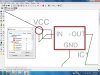
5)There is a button "R2" use to name parts R1, R2, R3...... not 3.4k
6)There is a button "10k" use ti to assign a value. 10k 1/2 watt 5%.
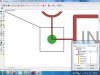
7)I found occurrences where two resistors were on top each other. This makes things work strangely! If one part is connected and the other is not then Eagle will say part not connected but I looks like a part is connected. If both are connected then eagle puts a green dot on the pin which should not be there.
7)There was a spot where three grounds were on top each other. You might have used the copy button on that part.
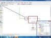
8)You like to have parts touching. Please have a small green net between each part. This way you can see if they are really connected.

I did not fix everything just changed some Rs and Cs to get you started.
 

Attachments

  • pic16f872 board.zip
    28.3 KB · Views: 222
Made some more changes.
There are/were some spots where the nets (green lines) are two/three layers deep. Nets on top of nets also adds to the confusion.
 

Attachments

  • pic16f872 board.zip
    28.3 KB · Views: 225
Last edited:
Status
Not open for further replies.

Latest threads

New Articles From Microcontroller Tips

Back
Top