Continue to Site

Welcome to our site!

Electro Tech is an online community (with over 170,000 members) who enjoy talking about and building electronic circuits, projects and gadgets. To participate you need to register. Registration is free. Click here to register now.

  • Welcome to our site! Electro Tech is an online community (with over 170,000 members) who enjoy talking about and building electronic circuits, projects and gadgets. To participate you need to register. Registration is free. Click here to register now.

won't monitor RPI1031

Status
Not open for further replies.

MrDEB

Well-Known Member
have adrino code but trying to implement into Swordfish using a Tap-28 board.
The leds are enabled on a port low
the code just stops but it should keep going to monitor the tilt sensor RPI1031.
Just a nudge in right direction as it enables an led but repositioning the sensor it won't do anything. I have to cut power to the pic then repower it up and maybe it will assume new position.
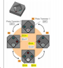
As I understand it the two outputs from the breakout board go LOW/LOW , LOW/HIGH , HIGH/ HIGH HIGH , HIGH / LOW , LOW / HIGH My plan is to add up the s1 and s2 to indicate which led is enabled. I really only need two led outputs instead of 4
Code:
{
*****************************************************************************
*  Name    : UNTITLED.BAS                                                   *
*  Author  : [select VIEW...EDITOR OPTIONS]                                 *
*  Notice  : Copyright (c) 2013 [select VIEW...EDITOR OPTIONS]              *
*          : All Rights Reserved                                            *
*  Date    : 3/30/2013                                                      *
*  Version : 1.0                                                            *
*  Notes   :                                                                *
*          :                                                                *
*****************************************************************************
}
Device = 18f2420
Clock = 8
//Config OSC=HS
Include "InternalOscillator.bas"
Include "utils.bas"
//Include "convert.bas"
Dim s1 As PORTC.4
Dim s2 As PORTC.5
Dim led2 As PORTB.3
Dim led1 As PORTA.3
Dim x As Byte
Dim tilt_s1 As Byte 
Dim tilt_s2 As Byte
Dim position As Word
dim tilt_pos as integer 
dim index as integer 
Input (s1)
Input (s2)

High (led1)
High(led2)
//tilt_s1 = 2
//tilt_s2 = 3

Output (led1)
Output (led2)
SetAllDigital


While true
      
      If s1 =0 Then tilt_s1 = 1
      EndIf
      If s1 =1 Then tilt_s1 = 2
      EndIf
      If s2 =0 Then tilt_s2 = 1
      EndIf
      If s2 =1 Then tilt_s1 = 2
      EndIf
      tilt_POS = tilt_s1 + tilt_s2
      if tilt_pos = 2 then led1 = 0
      delayms (300)
      toggle (led1)
      endif
     
      if tilt_pos = 4 then led2 = 0
      delayms(300)
      toggle (led2)
      endif
      tilt_pos = 0
     Wend
 
some progress but very little

still have to reset the pic for new data from sensor
Code:
{
*****************************************************************************
*  Name    : UNTITLED.BAS                                                   *
*  Author  : [select VIEW...EDITOR OPTIONS]                                 *
*  Notice  : Copyright (c) 2013 [select VIEW...EDITOR OPTIONS]              *
*          : All Rights Reserved                                            *
*  Date    : 3/30/2013                                                      *
*  Version : 1.0                                                            *
*  Notes   :                                                                *
*          :                                                                *
*****************************************************************************
}
Device = 18f2420
Clock = 8
//Config OSC=HS
Include "InternalOscillator.bas"
Include "utils.bas"
//Include "convert.bas"
Dim s1 As PORTC.4
Dim s2 As PORTC.5
Dim led2 As PORTB.3
Dim led1 As PORTA.3
Dim x As Byte
Dim tilt As word 

Dim position As Word
dim tilt_pos as integer 
dim index as integer 
Input (s1)
Input (s2)

led1=1
led2=1
//tilt_s1 = 2
//tilt_s2 = 3

Output (led1)
Output (led2)
SetAllDigital


While true
      
      If s1 =0 and s2 = 0 Then tilt = 1     // 
      EndIf
      If s1 =1 and s2 =0 Then tilt = 2
      EndIf
      If s1 =1 and s2 = 1 Then tilt = 3
      EndIf
      If s1 =0 and s2 = 1 Then tilt = 4
EndIf
    if tilt = 1 then led1 = 1 
       led2 = 0
      delayms (1000)
      led2 = 1            // leds off
      led1 = 1
    endif
    tilt = 0 
      
    if tilt = 2 then led2 = 0 
       led2 = 0
       delayms (1000)
       led2 = 1            // leds off
       led1 = 1
    endif
    tilt = 0   
    if tilt = 3 then led1 = 0     // both on
        led2 = 0
        delayms (1000)
        led2 = 1            // leds off
        led1 = 1
    endif
     tilt = 0   
    if tilt = 4 then led1 = 1 //and led2 = 1
      delayms(1000)        // blink once
      toggle (led1)
      toggle (led2)
      delayms(1000)
    endif
      
    tilt = 0 


     Wend
 
Tilt Sensing with the RPI-1031:

The RPI-1031 available from sparkfun is a pretty simple (heck, it is dead simple) sensor for sensing when it is tilted. And it does this really well. But it seriously only does that. If it is not tilted, it freaks out and reports tilt anyways.

It actually just uses a metal ball that rolls around inside (you can hear it moving around when you tip it). Because of how it is made, the ball is always up against one side even when it is flat. Unfortunately this means you can never know the difference between a reading, and it being flat, only changes in reading.
 
I read all that and almost abandoned the idea of using it until I realized that if I only monitor one side of each sensor (use two that are tilted at a 45 degree angle where I monitor only the top two photo sensors in the chip.
I have tried using a standard tilt sensor but the sample from A was $17.50 each while sample from B was too "buggy" or unreliable.
I realize how simple the RPI 1031 is just trying to get it to do its thing. I realize this may be the wrong path. I even considered fabricating a sensor.
 
Yes it should be easy

here is a diagram of internal workings. My posted code seems to detect tilt but won;t do it continusily. It reads, enables lED and stops. I reset pic and it read new tilt direction.
 

Attachments

  • sen10621.png
    sen10621.png
    162.8 KB · Views: 155
First off your code is all wrong your reading a dumb switch that can't tell you witch side switched.
That's from my take of this thing, You have a bunch of "if then" in a loop that test for true that ending up false.
That ends your loop.

Well it can tell if one of the two switches make. This is what you want to do you take a reading to find out what state its in.
Code:
dim state_A as bit
dim state_B as bit
dim sw_1 as portX
dim sw_2 as portX
dim led_1 as portX
input (sw_1)
input (sw_2)

while true 
       if sw_1 = 0 then 
          state_A = 1
      endif 
       if sw_2 = 0 then 
          state_B = 1
       endif

    if state_A =1 then
      high (led_1)
      delayMS(1000)
      state_A = 0
    elseif state_B = 1 then 
      low (led_1)
       delayMS(1000) 
      state_B =0
    endif
wend
I didn't do the both on state or the both off you can add them.
 
Last edited:
Where he find that picture in post 6 If you want code that picks all 4 states I'll post it for you.
 
I contemplated using an accelerometer but cost. Need to research further as my present tilt switch is a carnival cruise ship. Full of crap.
Even contemplating making a simple tilt switch using a duel channel optical sensor and a weighted wheel but the accelerometer idea, now that you brought it up looks better every day.
Going to revise my code as per Burt suggestion as I want to get that code working anyway. I felt that yes toooo many if then's. Even considered using a select case statement.
Going to edit using Burts suggestion. THANKS
Hey Burt you ever get the washing machine project done. Curious how the clear vinyl for toner transfer worked.
 
It was done when I posted the coin counter video. How you think i pay the bills LOL.

And where did you find the pic in post 6 there four states sw1 on, sw2, on both on or both off but there data sheet doesn't show anything like that.
 
https://microcontrollershop.com/product_info.php?products_id=4573
I guess I was looking at wrong accelerometers. The units I was looking at were $15-$60 each. Sparkfun has a breakout board for $12
This is an analog output. Just connect to ADC inputs and pull the memory pin high. Drop the Vcc to 3v as the pic is running on 5v may for accuracy, another voltage reg.
This would solve several issues but soldering a OFN chip might be exciting as the smoke circles to the heavens from cooking the pcboard--lol. Guess I am going to have to learn how to solder these babies to a board using a hot plate.
 
snag on using accelometer

slight snag in using accelerometer.
But I Need A Cleaner Reading

If you need a clean reading during movement, you need something this article won’t provide, and that is a gyro and an accelerometer working in combination. Together they form something called an IMU – Inertial measurement unit. Correctly setup, and gyro is able to kick in where an accelerometer leave off, and vise versa. A gyro is great at measuring rotation, but has no understanding of orientation. And an accelerometer is good at determining orientation, but has no ability to keep track during rotation.
back to the drawing board
 
What the heck you trying to do make the dead stand and walk or is it just to see if the bike rider moved his head? The tilt switch will work if you code it right.

Your code is no where near the arduino code you linked.

All you have to do is put the sensor flat on top of your head then read it and save your started state

sw1 sw2 can only be one of four things both on, sw1 on sw2, off both off, or sw1 off sw2 on

I showed you how to do two states which would work to see if your shaking your head.

If you want all four put the switches on say portb 0,1 and mask off the rest and read the port first to bits you'll get a 11,10,01,or a 00 guess what you can now pick out right left looking down looking up.
 
Tilt Sensor

Mouser Tilt Sensor

These are probably your best choice.

An accelerometer in a leadless package will be beyond you assembly capabilities. Also, a digital output accelerometer (I2C or SPI), while offering many advantages, is likely beyond your programming ability (sorry, but a reasonable observation based on your body of collected posts across a number of forums).

The MiniSense 100 Piezo sensor from Seeed has some intriguing possibilities for your application and is only $2.85 but engineering a successful design has some major challenges. I'm only listing it here because it could be a unique solution, not as a recommendation for you to consider. I'm not sure how well it would work without some tests - it's just made me think.

Piezo Sensor Data Sheet
 
slight snag in using accelerometer.

back to the drawing board

Ummm. No. Every iPhone on the planet uses an accelerometer to sense orientation. I believe the number is 3.8 million now...per month...being manufactured. No gyro is required to measure tilt.
 
The tilt sensors Jon linked to are basically the same as the samples I received from signal Quest and Select Controls. The Signal Quest units were very iffy not really a definite ON / OFF but the Select Controls worked very well but at $17.50 each I started looking elsewhere. I am going to order the sensor Jon linked to https://learn.adafruit.com/tilt-sensor and give it a go. I found similar couple weeks ago but were from Europe so shipping was out of the question.
While waiting for parts I plan to get the code Burt posted to work.
And YES the QFN soldering is not my cup of tea.
The https://www.seeedstudio.com/depot/piezo-sensor-minisense-100-p-426.html?cPath=144_146 looks interesting. Need to study this one futher.
Thanks again guys
 

Please don't waste your time with this. Just trust me that there are issues you don't understand in designing a solution around this part and I will offer not a single word beyond what I just said in engineering a workable result.. I believe the part has an interesting potential but considerable knowledge of piezo electronics principles will be needed to achieve a workable result if it's even possible.
 
ordered 4 of these https://learn.adafruit.com/tilt-sensor
hacking at the code Burt posted but no real results yet. I should just wait for parts and go back to square one with original design.
using the part from seedstudio is on the back shelf. Want to go the KISS route at this point.
 
Sucked in again. I don't f'ing believe it.

The RPI-1031 should be the easiest dang sensor in the world to use. If you look at the picture of the internal workings you posted, the cavity with the ball is a square. A unique output is generated when the ball is in each corner. This should be perfectly clear from the picture.

What you have most likely failed to understand on the hardware side is that the view you posted shows the sensor (and circuit board) in the vertical position. Hold the board vertically and rotate it about its center. When you've rotated just past 45 degrees....ker-lunk...the ball rolls to the next corner where it will stay for the next 90 degrees of rotation. It's designed to indicate which end is up on a cell phone or camera, and there are exactly four possibilities.

It should be a ten minute exercise to verify this using your PICkit 2 logic I/O Tool or a DVM. Follow the Sparkfun schematic connections for power, ground and the two output lines. Yes, power and ground must be connected no matter how inconvenient you find it.

So, a tilt of >45 degrees is needed to change states. If you get your ear to touch your shoulder, this should work. Perhaps not the best design choice, ya think? All may not be lost though. If you incline the board from vertical (incline the plane of the board), a smaller amount of tilt will be needed to move the ball from the rest position to either of the other possible corners. In fact, I would incline the board to maybe 15 - 20 degrees from horizontal so that a small tilt will cause the ball to move to the other corner while still biasing it to return to the rest position when not tilted.

So I think a basic lack of understanding explains the sensor problems. But what explains the software problems? This is like basic, trivial stuff. Fundamental stuff learned on page 2 of any guide.

To put in simply, your code is screwed up beyond belief. Lets start at the beginning:

1. You have had nothing but problems making the internal oscillator work. Unless you verify that it is working, assume it is not. How do you know if it's working at the right speed? Toggle an LED every time through the program loop. Stupid? Yes. Simple to do and saves a huge amount of time during program Dev because of errors in oscillator setup? ABSOLUTELY. The TAP-28 has provision for 4 LEDs. Spend 20 cents and solder another one in.

2. Geez. You have all the setup for the port pins screwed up. FIRST, use SetAllDigital. NEXT, define pins as inputs or outputs. THEN set them high or low as you desire. You have this completely backwards. You have to set the pin to digital and define it as an output before you set a level.

3. Now, start with a simple program. You have two inputs from the sensor. You have two LEDs. LED1 = Sensor1 and LED2 = Sensor2. Loop. Rotate the board and watch the lights change.

This should be 5 minutes of no-brainer programming activity. If you can't get this to work in 10 minutes, put everything in a cardboard box and donate it to the scouts.
 
Last edited:
Status
Not open for further replies.

New Articles From Microcontroller Tips

Back
Top