matthewwren
New Member
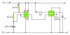
OK, I have only built 2 electronics circuits before. The first was a flip-flop, and the second was a d-type flip-flop. Now I have designed a logical diagram of a simple calculator circuit using one of these simulators. All works fine. Now the hard bit, actually translating that logic diagram into a circuit. My first dilemma is wiring up a 4013 chip. I thought, ok simple, just +9v into v+ and 0v to ground. But it doesn't behave as i expect, in fact Q1 always seems to have output even if i ground data in and clock. Can someone explain to me how to correctly wire a 4013 chip.