Continue to Site

Welcome to our site!

Electro Tech is an online community (with over 170,000 members) who enjoy talking about and building electronic circuits, projects and gadgets. To participate you need to register. Registration is free. Click here to register now.

  • Welcome to our site! Electro Tech is an online community (with over 170,000 members) who enjoy talking about and building electronic circuits, projects and gadgets. To participate you need to register. Registration is free. Click here to register now.

Wireless Mic Schematic - help please

Status
Not open for further replies.

DDasha

New Member
I am having a difficult time understanding why my circuit is not working.

Any help would be GREATLY appreciated!! thank you

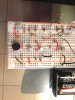
I have attached the link to the schematic and images of my circuit...

Wireless microphone schematic


**broken link removed**[/IMG]

**broken link removed**[/IMG]
 
hi,
As explained RF circuits on project boards are prone to problems.

In addition it appears you have at least two wiring errors.
The top left 10K [R1] is shorted out and Q1 base to R2 and C1 is in the wrong hole.??
 

Attachments

  • 2qtj1pv.jpg
    2qtj1pv.jpg
    52.5 KB · Views: 422
I see very old metal-case transistors in the circuit. Maybe they are the BC107 transistors that I used in my first job at Philips in 1967?
Then the transistors are 44 years old.
 
Nope, the transistors are 2N2222A, written we can see.

For an info, I've tried many transmitters like this on my breadboard :), but not to recommend.

The thing is, if you want to compensate for the stray capacitance, at least the 33pf might be a variable one. L1 looks ugly, need re-winding for sure.

Look this coil and compare it with yours :)

**broken link removed**

Lots of wiring errors as like eric already pointed out. Study the breadboard configuration first.
 
In addition to the problems of the breadboard and the poorly made coil, why are you making the crappy FM transmitter anyway? Its performance is HORRIBLE!
1) It doesn't have a voltage regulator so its radio frequency changes as the battery voltage runs down.
2) It doesn't have pre-emphasis (treble boost) like all FM radio stations so the de-emphasis in all FM radios will make the sound muffled without high audio frequencies.
3) It doesn't have much power so its range might be as far (or as short) as you can talk loudly.
 
Status
Not open for further replies.

Latest threads

New Articles From Microcontroller Tips

Back
Top