Anthony Diorio
New Member
Hi All
New around here probably 90% of tech talk will go right over my head. Proof of that is the question I have below.
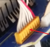
I am a trying to replace the input selector in my dsp a2070. it is soldered to a pcb I can not figure out how to release this type wire to board connector so I can remove pcb from unit Iuploaded a picture and would appreciate if someone familiar with this type connection can tell me how to remove it. Only marking I see is JST

Thanks
Anthony
New around here probably 90% of tech talk will go right over my head. Proof of that is the question I have below.
I am a trying to replace the input selector in my dsp a2070. it is soldered to a pcb I can not figure out how to release this type wire to board connector so I can remove pcb from unit Iuploaded a picture and would appreciate if someone familiar with this type connection can tell me how to remove it. Only marking I see is JST
Thanks
Anthony

")
