Electro Tech is an online community (with over 170,000 members) who enjoy talking about and building electronic circuits, projects and gadgets. To participate you need to register. Registration is free. Click here to register now.
Welcome to our site! Electro Tech is an online community (with over 170,000 members) who enjoy talking about and building electronic circuits, projects and gadgets. To participate you need to register. Registration is free. Click here to register now.
anyone have an idea for how i could make a blade for a savonius wind turbine as effective as possible? the wind turbine will be in this size**broken link removed**
As any sailboat racer will tell you running downwind is the slowest point of sailing. Beating to windward is the next best. To really fly you need to be on a beam reach. So make a device that is always on a beam reach and the world will beat a path to your door...so to speak.
So you're 13, if you can design a wind generator you can see the similarity between a sail with the wind behind the boat running downwind and the half cylinder of a savonius vertical wind turbine. It would have taken you a few clicks to google the rudiments of sailing. Realizing that the static force on a surface pales in comparison to the lift generated when a fluid flows over the same surface. You might be trying to solve the wrong problem.
Beam Reach - A point of sailing where the wind is perpendicular to the boat and the sail is trimed to generate the maximum amount of lift. The boat proceeds throught the water at it's maximum speed.
13? great to have you here - maybe there is hope for the next generation.
seriously, as the document says, the savonius design operates on a drag principle while the blade based turbines use aerodynamic lift. You would need to minimize the drag of the one side and maximize the drag of the other side. This is the same effect as a downwind run. I could see how some one could measure the drag of different designs and then pick the one with the greatest differential.
By the way, I would alter the savonius design a bit by seperating the generator from the blade section so you could try different blade designs easily.
there are other vertical designs that are more efficient because they use lift. like: **broken link removed** http://www.greenwindmill.com/
and one other that i couldn't find a link to but it uses curved blades that bow outward and is certainly the most gracefull looking.
The Savonius style of rotor is (i think) inherently inefficient.
The only way to improve the wind action that i can see,
is to mask or shield the wind from the half that is detracting.
This could concievably be done by using a tail which would place
such a shield across the half that detracts.
***************************
Since my explanation of this concept is poor,
i will try to explain it another way.
The savonious style of rotor has one side moving into the wind.
This side could be shielded by a movable part with a tail.
The movable part with a tail would be positioned by the wind,
and would sheild the section of the savonius rotor which
moves into the wind.
***************************
That explanation is not much better.
But it will have to do.
**************************
I can see no way to improve the efficiency of a savonius style
rotor very far, this suggestion of adding a separate part to act
as a sort of wind-guide or shield should make a big difference,
even though it does not address the efficiency of the rotor
but changes the way the wind blows upon it.
Best of luck with your project,
and let us know how you get on.
John
these are blades with lift , not drag.
i can cut one in a night , few hours , then epoxy the segments together
they are surprisingly rigid, being that they are made of foam
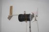
the alternator is three phase with 16 poles 12 coils and can put out 170 watts , with larger blades .
hi,
i just want to ask what the problem is here. i have made a HAWT (horizontal axis wind turbine) and was wondering why i only get about 2 volts out of a large dc motor when i spin the blades. also i only get voltage when i spin the blades, not when they are spinning without help. do i have the wrong kind of motor. what do you suggest?
a 90 V PMDC treadmill motor makes a much better wind turbine generator, because the RPMs needed to produce power is a lot less.
hence to start charging a 12Volt battery ,the RPMs needed are alot less than if it was a 24V motor.
you could allways boost the voltage .
you would need a PIC controller with PWM ,a FET , an inductor and a fast diode
what you do is pulse the inductor with the fet and the generator in one loop ,when the inductor is still releasing energy and the FET is off the current has no where to go , so you place the diode above the drain (between the inductor and the fet) pointing twards your battery.
In the attached ckt..
M1 M3 and R2 are optional , as is the Cap,
your motor/generator would go where the three phase Alternator and the diode bridge is.
my wind turbine doesn't light up the lightbulb =( i did exactly as it said on the website but the lightbulb still won't light up... It's a 6,5 watt lightbulb do I need a different one??? Or doesn't it work with 4 magnets spinning above 4 coils of wire??
This site uses cookies to help personalise content, tailor your experience and to keep you logged in if you register.
By continuing to use this site, you are consenting to our use of cookies.