Continue to Site

Welcome to our site!

Electro Tech is an online community (with over 170,000 members) who enjoy talking about and building electronic circuits, projects and gadgets. To participate you need to register. Registration is free. Click here to register now.

  • Welcome to our site! Electro Tech is an online community (with over 170,000 members) who enjoy talking about and building electronic circuits, projects and gadgets. To participate you need to register. Registration is free. Click here to register now.

Will this telephone circuit work?

Status
Not open for further replies.

Megamox

New Member
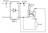
I only know a little about the UK phone system, i think the on hook voltage is around 48vDC, the ring voltage is about 100v AC @ 20hz, the off hook voltage is 10-15v. I wanted to try the circuit below to see if it would answer the phone but just wanted to check thats its okay. The opto-isolator is tripped with the ring signal into temporarily loading the line with the 330 ohm resistor making the telephone company think its been picked up. Once the ring stops the resistor is unloaded and the line goes dead... at least thats what i think would happen?

Thanks in advance for any info.

Megamox
 

Attachments

  • telephoneanswer.jpg
    telephoneanswer.jpg
    16 KB · Views: 428
No it won't work. The resistor must be on the line side to trip the ring. There has to be a DC loop to trip the ring and hold the call.

You should position C1 between Z1 and R1.

I doubt whether the transistor in the opto can withstand the ring voltage.

Also, there needs to be a delay to hold the transistor on while the ring is tripped.

(I worked in the telephone industry for many years)
 
Simply use a glimm (small neon indicator lamp) without serial resistor.
It fires about 70...90V, give a short to line, and the ring will stop before You hear it...
 
Status
Not open for further replies.

Latest threads

Back
Top