Electro Tech is an online community (with over 170,000 members) who enjoy talking about and building electronic circuits, projects and gadgets. To participate you need to register. Registration is free. Click here to register now.
Welcome to our site! Electro Tech is an online community (with over 170,000 members) who enjoy talking about and building electronic circuits, projects and gadgets. To participate you need to register. Registration is free. Click here to register now.
it's the same wmmullaney...but unfortunately it doesn't work, you must
find transistor with the specific properties to make it work.
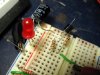
instead of that you can make a pretty nice led flash light with touch on button! put the transistor in the correct way and let the base float... see what happens if you touch it
Yep, worked for me too. Just put one together. Made my first SED in the process (I've destroyed LEDs before but never quite so audibly), but fixed the wiring and it's just sitting there now, flashing away happily to itself.
Torben
[Edit: I don't know if this can be simmed in LTSpice. If so, I don't know how.]
I don't know how low a voltage this can be made to work on but the one I built wants 12V. 2-transistor flashers (astable multivibrators) can work much lower and only have a few more parts. They also don't rely on making a transistor work as a tunnelling diode, which is neat but I think just a proof-of-concept.
Torben
[Edit: I posted before coffee--my post should have been aimed at wmmullaney; I know Nigel already knows this stuff. Googling "2-transistor flasher" will indeed fetch you many schematics, explanations, and calculations for working out the timing.]
Yeah, the disadvantages of this circuit are that you need a larger value capacitor and a higher voltage than the astable 2 transistor circuits. This is in addition to the fact that you probably get longer transistor life and more accurate time intervals with the astable circuit.
If anyone's having trouble finding good explanations, start here and **broken link removed**.
EDIT: Sorry for the confusion, but it appears the first link it showing actual current flow, but the second is conventional (+ to -).
yes it does work with your 47K modification... and with 100K but only with
2n2222 in metal can! i also tryed 2n3904 and it didn't worked... it lights stable i haven't tryed bc547..
1k resistor fills the capacitor too fast? why the schematic says 1K???
Torben said:
[Edit: I don't know if this can be simmed in LTSpice. If so, I don't know how.]
yes it does work with your 47K modification... and with 100K but only with
2n2222 in metal can! i also tryed 2n3904 and it didn't worked... it lights stable i haven't tryed bc547..
1k resistor fills the capacitor too fast? why the schematic says 1K???
I haven't tried with a 3904, but the first 2 2222As I tried both worked (TO-92 packages). I've also run it with various capacitor sizes and 1K and 10K resistors and the only thing that changed was the flash rate and length.
i don't see how LTspice can simulate such thing... it's an undocumented function...
I don't know what you mean by "undocumented"; it's quite well documented actually. The earliest article I found in 10 minutes with google was from a 1975 issue of Popular Electronics magazine (**broken link removed**. I'd agree that it's not in the transistor datasheet, but that doesn't mean that it couldn't be modeled.
yes it does work with your 47K modification... and with 100K but only with
2n2222 in metal can! i also tryed 2n3904 and it didn't worked... it lights stable i haven't tryed bc547..
1k resistor fills the capacitor too fast? why the schematic says 1K???
i don't see how LTspice can simulate such thing... it's an undocumented function...
It has nothing to do with LTspice and everything to do with the transistor spice models. I have never seen a model that includes Vbe breakdown, much less the negative resistance of the Vceo breakdown.
It has nothing to do with LTspice and everything to do with the transistor spice models. I have never seen a model that includes Vbe breakdown, much less the negative resistance of the Vceo breakdown.
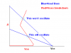
It is a function of where the load line intersects the VI curve of the Vceo breakdown. The red line below is representative of the general shape of the Vceo breakdown VI curve. The blue lines are examples of load lines that will and will not oscillate. As you can see, in order for oscillation to occur, the load line has to intersect the breakdown curve in its negative resistance portion. The one that doesn't oscillate intersects the positive resistance portion of the curve, and is therefore a stable bias point.
The oscillator needs to satisfy following conditions to oscillate:
The supply voltage needs to be high enough for the transistor to break down.
The series resistor needs to limit a current to a low enough level to allow the transistor to turn off after the capacitor has discharged.
It won't oscillate if:
If the resistor is too low - the transistor will just remain on after the capacitor has discharged as the current through it will be high enought to keep it conducting.
If the power supply voltage is too - the transistor will never break down.
This site uses cookies to help personalise content, tailor your experience and to keep you logged in if you register.
By continuing to use this site, you are consenting to our use of cookies.

")