Continue to Site

Welcome to our site!

Electro Tech is an online community (with over 170,000 members) who enjoy talking about and building electronic circuits, projects and gadgets. To participate you need to register. Registration is free. Click here to register now.

  • Welcome to our site! Electro Tech is an online community (with over 170,000 members) who enjoy talking about and building electronic circuits, projects and gadgets. To participate you need to register. Registration is free. Click here to register now.

will this circuit work?

Status
Not open for further replies.
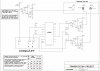
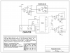
Why is your schematic as big as, no bigger than my entire neighbourhood?
I cropped it to make it a little smaller.

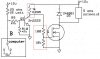
You had your transistor connected to +12V but not connected to the Mosfet.
I corrected it.

You can use a tiny little surface-mount transistior if you can handle it.

I would not use the tiny little surface-mount power resistor because it is difficult to cool it.

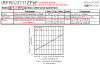
The tiny little surface-mount Mosfet will probably melt if it tries to drive 2.4A. Its resistance will be about 1.2 ohms and it will try to dissipate 6.9W. But it cannot be bolted to a heatsink, it is cooled a little by the copper on a pcb.

Ooops...thanks for the correction
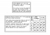
 ;) Is it always better to "over-do" the ratings rather than get close to them as far as MOSFET's go? Will the higher rating produce an overall lower temperature? In you calculations above, what information on the data sheet led you to the 1.2 ohms and 6.9W? (just so I can look and figure it out myself) Ive attached another MOSFET...This one should be plenty big enough. Last one, there are several different types of resistors and Im not to sure which type I should be working with (for the 25 ohm 10 watt one) should it be a standard power resistor? THANKS AGAIN!!!

EDIT: would this be a good canidate for the 25ohm resistor? ((Attached))
 

Attachments

  • IPP50CN10N_Rev1.03.pdf
    490.3 KB · Views: 288
  • resistor.pdf
    123.2 KB · Views: 177
Last edited:
The tiny little Mosfet has a pretty high on-resistance. With 2.4A through it (12V/5 ohms= 2.4A) then it is going to get hot.
Its tiny case is difficult to cool.

Its on-resistance is 0.15 ohms max when its case is cooled to 25 degrees C somehow. Its on-resistance is 1.9 ohms max when it is hot.
Assume its chip is halfway between 25 degrees C and its max temperature of 175 degrees C. then its chip is 100 degrees C. Then its on-resistance is about 1.2 ohms max.
Its power dissipation is then 2.4A squared times 1.2 ohms= 6.9W.
Without a heatsink then its chip is (48 degrees rise per Watt x 6.9) + 25= 356 degrees C which is way more than enough to destroy it.

The problem is that it is an old Mosfet with a very high on-resistance and it is in a tiny case that is difficult to cool.
The other Mosfet is almost the same.

A good Mosfet is the IRF3711Z but its max voltage is only 20V. Mosfets with higher voltage ratings are available.
Its on-resistance is only 0.006 ohms max when it is cold and is probably 0.01 ohms when warm. It will heat with 2.4A squared times 0.01 ohms= only 0.06W. 100 times less than the Mosfet you first selected. It won't even feel warm.

I found a power resistor in a small aluminum case with mounting holes for attaching to a heatsink and little cooling fins. Its max power rating is 25W. Ordinary 10W power resistors are in a pretty big cement case. They get extremely hot.

Your amazing Audio. Thanks for all the help and not just giving me the answers. Im learning a lot. Not to keep beating a dead horse but in the datasheet for the MOSFET you recommended (IRF3711Z) I still can't figure out how your getting .006 ohms cold and about 0.01 warm? I dont see either of these anywhere on the data sheet. Can you guide me one more time and help me figure this out? Thanks again...your extremely helpful!!!

Strokedmaro
 

Attachments

  • irfr3711zpbf.pdf
    262.9 KB · Views: 173
Last edited:
You found the tiny little surface-mount Mosfet. It should work fine if its 20V max voltage rating will be OK in your circuit.

All its details are on its datasheet.
 

Attachments

  • IRFR3711Z.PNG
    IRFR3711Z.PNG
    31.1 KB · Views: 160
Once again your awesome! Ive attached a 25W resistor I found based on your recommendations. Since the load will be almost 25% (7.6W) the rated wattage, will I even require a heatsink? Without a heatsink it says it would be good up to 12.5W @ 25 degrees. In the graph it shows it would be about 20 degrees C but thats with a "standard heasink" right? Also, the max voltage this circuit should have is 13.8vdc so Im guessing the 20V max rating WILL be ok? THANK YOU, THANK YOU, THANK YOU!!!
 

Attachments

  • 25 ohm 25 watt.pdf
    142.3 KB · Views: 188
Last edited:
one more....why in the world would'nt you use a MOSFET over a bi-polar like a TIP41 for example? Is it just the price? It would seem to me that they operate much cooler in a smaller package and able to carry many times the current..I dont understand.

in the schematic you posted do you add the resistors up in series to figure out there wattage? I understand the 1k (.19W at 13.8Vdc through the 2n222) but what about the 100 and 10k? The total resistance to the source of the MOSFET would be 11100 ohms (.017W at 13.8) so would 1/8W work for these?
 

Attachments

  • untitled.JPG
    untitled.JPG
    42 KB · Views: 166
Last edited:
Once again your awesome! Ive attached a 25W resistor I found based on your recommendations. Since the load will be almost 25% (7.6W) the rated wattage, will I even require a heatsink? Without a heatsink it says it would be good up to 12.5W @ 25 degrees. In the graph it shows it would be about 20 degrees C but thats with a "standard heasink" right? Also, the max voltage this circuit should have is 13.8vdc so Im guessing the 20V max rating WILL be ok? THANK YOU, THANK YOU, THANK YOU!!!
The HS25 resistor is fine without a heatsink. with only 7.6W it will be pretty warm but not too hot.
 
one more....why in the world would'nt you use a MOSFET over a bi-polar like a TIP41 for example? Is it just the price? It would seem to me that they operate much cooler in a smaller package and able to carry many times the current..I dont understand.
We talked about using a cool little Mosfet instead of a big hot TIP41 transistor.

in the schematic you posted do you add the resistors up in series to figure out there wattage? I understand the 1k (.19W at 13.8Vdc through the 2n222) but what about the 100 and 10k? The total resistance to the source of the MOSFET would be 11100 ohms (.017W at 13.8) so would 1/8W work for these?
The transistor saturates with a voltage loss of about 0.2V so the 1k resistor will have 13.6V across it. Its power dissipation is (13.6V squared /1k ohms)= 0.185W.
A 1/4W resistor is fine.
The gate of a Mosfet draws no DC current. When the transistor is turned off then the 1k, 100 and 10k resistors have a current of 1.2mA. Then the 100 ohm resistor dissipates (1.2mA squared x 100 ohms)= 0.00014W and the 10k resistor dissipates 100 times less.
Any size resistor is fine.
 
Update

Here is my new schematic. Using what Ive learned from Audioguru (Thank you, thank you!) Ive put this together. The text on the schematic didnt come out very clear so I blew it up into another pic. Will this work and are my pull up values on the 4028 ok? Thanks for the help everyone!!

EDIT: Oops..the MOSFETS are IRF3711Z's. I know these are overkill for the solenoid's which draw only about .5 amps but they are what I have (and necessary for the 5 ohm solenoid).
 

Attachments

  • TRANSMISSION PROJECT.JPG
    TRANSMISSION PROJECT.JPG
    190.4 KB · Views: 159
  • TRANS TEXT.JPG
    TRANS TEXT.JPG
    97 KB · Views: 136
  • 4028.PDF
    122.7 KB · Views: 292
Last edited:
Your schematic is huge. It is the size of my neighbourhood. It is covered in dots (can't you turn off the dots?).

It is not clear because you saved it as a fuzzy JPG file type instead of as a very clear GIF or PNG file type.

The 1k pullup resistors might not be able to be driven by the computer because their current is high. Use 22k instead.
 
Here is another shot at a better schematic...other than the pull-ups (which Ive updated already) do you see any other errors? Also, would it be possible for me to use 47k for the pull ups since I have a ton of those on hand? Should work fairly well right? Thanks again Audio....your invaluable.

~Strokedmaro~
 

Attachments

  • 80e harness current.png
    80e harness current.png
    26.7 KB · Views: 150
Your new schematic looks very clear.
Yes you can use 47k for the pullups.
 
Thank you Audio...anything else look wrong in my schematic? In particular the 4 diodes attached to the 3 outputs of the 4028 that controls the MOSFETS for the "A" and "B" solenoids.
 
Last edited:
Status
Not open for further replies.

Latest threads

Back
Top