Continue to Site

Welcome to our site!

Electro Tech is an online community (with over 170,000 members) who enjoy talking about and building electronic circuits, projects and gadgets. To participate you need to register. Registration is free. Click here to register now.

  • Welcome to our site! Electro Tech is an online community (with over 170,000 members) who enjoy talking about and building electronic circuits, projects and gadgets. To participate you need to register. Registration is free. Click here to register now.

Will this circuit work?

Status
Not open for further replies.

Rexlan

New Member
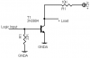
I want to provide a 12 volt signal to a small horn and have it sound for a 1/4 second (beep).

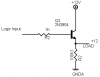
I'm using a PIC processor. Will this simple circuit work to do it? I had asked earlier using a FET but thought this would be much easier.

Thanks
 

Attachments

  • T-switch-2.png
    T-switch-2.png
    1 KB · Views: 240
  • T-switch.png
    T-switch.png
    1.1 KB · Views: 206
Last edited:
Depending on the resistance of your load (i.e. the horn), when the logic input is lo, the horn will be on, but when it is high it won't. At least that's what it looks like to me.
 
Depending on the resistance of your load (i.e. the horn), when the logic input is lo, the horn will be on, but when it is high it won't. At least that's what it looks like to me.

It will be on, but not audible. It needs some kind of on and off signal to sound.

Easiest way is to connect a self contained piezo buzzer between collector and V+. Most of them tolerate operating voltages from 3 to 24VDC.

It will sound when the logic output is high.

Boncuk
 
Last edited:
I saw an error in the schematic and updated it.
I do not have room for another device like a Pizzo ... must use the electric horn for the application. Trying to make it just beep as a warning indicator.

Thanks.
 
You're not really giving enough information for people to try and help. First off, you've got two schematics in your original post. Which one are you using? This schematic circuit you've got here:

t-switch-2-png.45350


might work but, I'm not sure what is going on with the other one.

For the above circuit, when the input signal is high the voltage at the line you have marked as "LOAD" will not be 12V. It will depend on the voltage drop across your load which in turn depends on its resistance. The voltage there will be:

signal voltage (you say 12V) - the voltage drop across the base resistor - Vbe

The lower the resistance of your load, the lower the voltage at the emitter of the NPN will be. We'll need more specifics on what it is exactly you want to make the noise with.

What Boncuk was saying about the horn being on but not audible might be the case if you are using something like an ordinary speaker. For instance, if you wanted to make the noise with a speaker, you couldn't just power it and have it make a sound. You would have to pulse the input on and off rapidly to make the sound. So if you wanted a sound of 1000 Hz, you'd have to turn the speaker on and off 1000 time per second. This wouldn't be difficult to do with a PIC, but it's something you need to be aware of if you're not already.

So, you'll need to give additional information. What is it exactly you are using to make the sound, what voltage is it designed to work at. What it is resistance. Everything you know or can find out about it, post it.

Lastly, you said that you want to use a 12V logic signal from a PIC to turn the horn on and off but very few PICs can work at that high of a voltage. Are you sure the one that you are using can tolerate a supply voltage of 12V?
 

Attachments

  • T-switch-2.png
    T-switch-2.png
    1 KB · Views: 385
You want to use a circuit similar to the attached circuit. Problem being you aren't giving any details as were asked for. How much current does the horn draw for starters? You would place the horn in the collector circuit as shown but without more info what you see is as good as it gets. The Diode in parallel with the horn is to prevent back EMF from toasting your circuit PIC.

Ron
 

Attachments

  • Buzzer.gif
    Buzzer.gif
    4.6 KB · Views: 210
Sorry for the confusion. I show 2 drawings only as ideas ... I don't know which will work if any.

The horn is a standard automotive 12v unit. I measured it a ~ 2 oms.

I'm using a processor and I can send about any signal to the transistor (or small FET). I do not want to blow it at full intensity ... just want to beep it like a low level warning.

I tried it with a 4.5 volt direct connection and it does not do anything. It seems to come to life around 9 volts DC.

I can not switch the low (ground) side because of the way it is wired already so I have to just put power on the line ... same as if you activated the switch manually.

Thanks for helping

Thanks.

**broken link removed**
 
Last edited:
The horn is a standard automotive 12v unit. I measured it a ~ 2 oms.

OK, all new game now. 12 Volt automotive horns draw considerable current. Based on what you measured the horn has a coil resistance of about 2 Ohms. That tells me 12 volts / 2 Ohms = 6 Amps. At 12 volts applied your horn will try to draw 6 Amps of current. You would be looking at a MOSFET for high side switching. In your above circuit your transistor would burn up real quick. This link is a good read on MOSFETs.

A simple approach would be to have your transistor in a circuit like I posted drive a small 12 volt coil automotive relay and let the relay switch the high side of the horn. Much the way the horn works in a car.

Originally I saw a "buzzer" as a small buzzer that would typically draw less than 100 mA and not a device like an automotive horn that draws considerable current. :)

Ron
 
Last edited:
OK ... thanks. I figured the horn would draw a lot current but hoped I could somehow just bleep it for 1/4 second or so. I only have 1" x 1.5" total space in the box so no room for a relay and extra parts.
I though about adding a series R to the horn but then it may not work at all ... guess I am defeated on this.

I had looked at the high side switching with the FET before that Mike helped me with ... and not enough room for components.
 
A MOSFET wouldn't really take that much more space than a basic switching transistor. The idea here is that a simple NPN switching transistor like a 2N3904 or 2N2222 just won't handle the load, even for short burst. Using a MOSFET as a high side switch would work if you can fit things in the box. For short durations heat should not be a big factor. The space limitations do preclude the relay approach though. :(

Ron
 
Status
Not open for further replies.

Latest threads

Back
Top