Electro Tech is an online community (with over 170,000 members) who enjoy talking about and building electronic circuits, projects and gadgets. To participate you need to register. Registration is free. Click here to register now.
Welcome to our site! Electro Tech is an online community (with over 170,000 members) who enjoy talking about and building electronic circuits, projects and gadgets. To participate you need to register. Registration is free. Click here to register now.
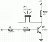
Murata's schematic of the oscillator for a piezo beeper uses a piezo with a 3rd electrode, the feedback electrode. The feedback electrode is out-of-phase to the main electrode (it is a Hartley oscillator) so the transistor has positive feedback.
I think it automatically oscillates at the loudest frequency of the piezo/helmholtz cavity.
This site uses cookies to help personalise content, tailor your experience and to keep you logged in if you register.
By continuing to use this site, you are consenting to our use of cookies.

")