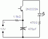
I'm trying to understand why this simple led flasher doesn't work. The concept is that the capacitor will charge enough (.6v) to turn on the transistor. The transistor will use up (discharge) the capacitor by switching collector/emitter turning the led on. The transistor will then switch off as the capacitor charges again.
On the breadboard with a small capacitor the led flashes once and turns off. I guess this is because the capacitor is fully charged and won't allow the DC current to pass through it anymore?
With a large capacitor the LED stays on all the time. I'm guessing this is because the capacitor is not fully charged so it allows the DC current to pass through?
Sorry I'm new to this and I'm trying to understand the concepts so I can hopefully design my own circuits later on.
Attachments
Last edited:
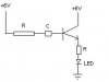
") Perhaps by using a feedback of some sort. After all the transistor is a switch so when it turns on I should be able to get an LED or something to discharge the capacitor no?
Perhaps by using a feedback of some sort. After all the transistor is a switch so when it turns on I should be able to get an LED or something to discharge the capacitor no?